Table of Contents
Advertisement
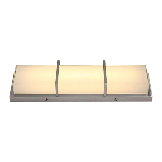
Model VBL3-12BNK
allen + roth
®
is a registered trademark
of LF, LLC. All Rights Reserved.
ATTACH YOUR RECEIPT HERE
Purchase Date
Questions, problems, missing parts? Before returning to your retailer, call our customer
service department at
RR20204
welcoming • sophisticated • inspiring
Model VBL3-20BNK
Model VBL3-20BZ
1-866-439-9800, 8 a.m. - 8 p.m., EST, Monday - Sunday.
Model VBL3-27BZ
Model VBL3-27CHP
Model VBL3-27BNK
VANITY LIGHT
1
For Damp
Location
ITEM
#0970854,1574013
0970855, 0970856
1129920, 1129919
MODEL
#VBL3-12BNK
VBL3-20BNK, VBL3-20BZ
VBL3-27BZ, VBL3-27CHP
VBL3-27BNK
Français p. 10
Español p. 19
Advertisement
Table of Contents

Related Manuals for Allen + Roth VBL3-27BZ


Summary of Contents for Allen + Roth VBL3-27BZ
- Page 1 • sophisticated • inspiring Model VBL3-27BZ Model VBL3-27CHP Model VBL3-27BNK Model VBL3-20BNK Model VBL3-20BZ Model VBL3-12BNK For Damp Location allen + roth ® is a registered trademark ITEM #0970854,1574013 of LF, LLC. All Rights Reserved. 0970855, 0970856 1129920, 1129919...
-
Page 2: Table Of Contents
TABLE OF CONTENTS Package Contents ......................... 2 Hardware Contents ....................... 2 Safety Information ......................... 3 Preparation ..........................5 Assembly Instructions ......................5 Care and Maintenance ......................8 Troubleshooting ........................9 Warranty ..........................9 PACKAGE CONTENTS PART DESCRIPTION QUANTITY Fixture Mounting Plate (preassembled to fixture (A)) Mounting Plate Screw (preassembled to fixture (A)) -
Page 3: Safety Information
SAFETY INFORMATION READ AND SAVE THESE INSTRUCTIONS. DANGER • For your protection and safety, carefully read and understand the information provided in this manual completely before attempting to assemble, install or operate this product. Failure to do so could lead to fire, electrical shock or other injuries that could be hazardous or even fatal. •... - Page 4 SAFETY INFORMATION Modifications not approved by the party responsible for compliance could void the user's authority to operate the equipment. The device complies with Part 15 of the FCC Rules. Operation is subject to the following two conditions: (1) this device may not cause harmful interference, (2) this device must accept any interference received, including interference that may cause undesired operation.
-
Page 5: Preparation
PREPARATION Before beginning assembly of product, make sure all parts are present. Compare parts with package contents list and hardware contents list. If any part is missing or damaged, do not attempt to assemble the product. Estimated Assembly Time: 30 minutes Tools Required for Assembly (not included): Flathead Screwdriver, Phillips Screwdriver, Wire Strippers, Pliers, Wire Cutters, Safety Glasses, Stepladder, Electrical Tape Helpful Tools (not included): A/C Tester Light, Do-It-Yourself Guide, Soft Cloth, Level... - Page 6 ASSEMBLY INSTRUCTIONS Remove mounting plate (B) from fixture (A) by removing mounting plate screws (C) from the edges of the fixture (A). Save mounting plate screws (C) for later use. Attach mounting plate (B) to outlet box (not included) using existing washers and outlet box screws or the machine screws (BB).
- Page 7 ASSEMBLY INSTRUCTIONS Unwrap BARE fixture wire from BLACK and WHITE BLACK fixture wires. Prepare wires by stripping 3/4 in. of insulation from wire ends using wire strippers (not included). Connect WHITE wire from fixture (A) to WHITE wire from outlet box using existing wire connector or wire connector (AA).
-
Page 8: Care And Maintenance
ASSEMBLY INSTRUCTIONS Attach fixture (A) to mounting plate (B) using the mounting plate screws (C) previously removed (Step 3, Page 6). NOTE: Before tightening mounting plate screws (C) completely, use level (not included) to check fixture (A) -- adjust if necessary. Restore power and test fixture (A). -
Page 9: Troubleshooting
TROUBLESHOOTING WARNING: Before beginning work, shut off the power supply to avoid electrical shock. PROBLEM POSSIBLE CAUSE CORRECTIVE ACTION 1. Power is OFF. 1. Make sure power supply is ON. Light does not come on 2. Faulty connection. 2. Check wiring and all connections. initially or no longer 3.
Need help?
Do you have a question about the VBL3-27BZ and is the answer not in the manual?
Questions and answers
I cant figure out how to change the bulb in my light I know that sounds strange but look at the picture of the light and you will understand
You do not need to change the bulb in the Allen + Roth VBL3-27BZ light fixture because it features an integrated LED light source.
This answer is automatically generated