Table of Contents
Advertisement
Quick Links
Contents
Safety Information................................................................................................................................................ 1
Warning...............................................................................................................................................................................................1
Warranty..............................................................................................................................................................................................1
Accessories......................................................................................................................................................................................... 2
Introduction........................................................................................................................................................... 2
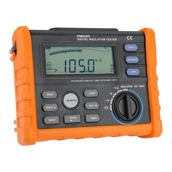
Front Panel..........................................................................................................................................................................................2
Display Screen.................................................................................................................................................................................... 3
Display Messages............................................................................................................................................................................... 5
Buttons................................................................................................................................................................................................ 7
Rotary switch...................................................................................................................................................................................... 9
Input Terminal.....................................................................................................................................................................................9
Function Description.............................................................................................................................................9
Power-Up Options.............................................................................................................................................................................. 9
Automatic Power Off........................................................................................................................................................................10
Hold Funcion.................................................................................................................................................................................... 10
Relative Measurement...................................................................................................................................................................... 10
Insulation Test Lock..........................................................................................................................................................................11
Storing Test Data.............................................................................................................................................................................. 11
Reading Test Data.............................................................................................................................................................................12
Delete Data....................................................................................................................................................................................... 13
Compare Function............................................................................................................................................................................ 14
Timer Function................................................................................................................................................................................. 16
MAX/ MIN/AVG..............................................................................................................................................................................18
DAR & PI......................................................................................................................................................................................... 19
Making Basic Measurements............................................................................................................................. 19
Measuring DC Voltage..................................................................................................................................................................... 19
Measuring AC Voltage...................................................................................................................................................................20
I
Advertisement
Table of Contents

Related Manuals for PEAKMETER PM5205

Summary of Contents for PEAKMETER PM5205
-
Page 1: Table Of Contents
Contents Safety Information..............................1 Warning.......................................1 Warranty......................................1 Accessories......................................2 Introduction................................2 Front Panel......................................2 Display Screen....................................3 Display Messages....................................5 Buttons........................................ 7 Rotary switch...................................... 9 Input Terminal.....................................9 Function Description.............................9 Power-Up Options....................................9 Automatic Power Off..................................10 Hold Funcion....................................10 Relative Measurement..................................10 Insulation Test Lock..................................11 Storing Test Data.................................... - Page 2 Measuring Resistance..................................21 Insulation Test....................................22 Replacing battery..............................23 Specifications............................... 24 Accuracy......................................26...
-
Page 3: Safety Information
Insulation Tester Safety Information This style of digital multimeter is designed and manufactured according to the safety requirements set out by the IEC61010-1 standards for electronic test instruments . Its design and manufacture is strictly based on the provisions in the 1000V CAT Ⅲ... -
Page 4: Accessories
warranty period is one year and begins on the date of shipment. Parts, product repairs, and services are warranted for 12 months except for misused, altered, neglected, contaminated, or damaged by accident or abnormal conditions of operation or handling.This warranty does not apply to fuses, disposable batteries. Accessories Item Test Leads... -
Page 5: Display Screen
Insulation Tester Display Screen Indicator Description Low battery Indicates when it is time to replace the battery. To avoid false readings, which could lead to possible electric shock or personal injury, replace the battery as soon as the low battery indicator appears. Indicates a test lock will be applied the next time you press Test Button on the meter,the test lock acts to hold down the button until you press Test Button again. - Page 6 Accessories Indicator Description Compare function is selected When compare function is selected,when the measuring value between upper limited value and lower limited value ,display this sign. Compare function is selected In insulation test mode, display the DAR value In insulation test mode, display the PI value Timer function is selected Store function is selected View the memory data,when the data is invalid,display---...
-
Page 7: Display Messages
Insulation Tester Indicator Description Continuity test function is selected Auto power off function is selected Insulation test Indicator.when the rotary switch at insulation position, this sign appers,when the test voltage is present ,the sign alternate on or off Source voltage rating for insulation test Timer unit Measure unit Display the Max,Min Avg value... - Page 8 Display Messages Indicator Description In insulation mode,indicates meter have detected the voltage on the input terminals LIVE In insulation mode,indicates the meter performs the auto discharge function.;not to touch DISC any input terminals in this mode. SAVE Store measuring data dEL n: Delete the selected data Delete all memorized data...
-
Page 9: Buttons
Insulation Tester Buttons... - Page 10 Buttons Description ○ Active store function: store the measureing data to memory ○ Active read function,to view the data store in memory; change cursor position. 1 : in dcv ,acv,continuty mode to view the max value,min value ,avg value, upper limited value, ○...
-
Page 11: Rotary Switch
Insulation Tester Rotary switch Position Function Turn off the meter power DC Voltage :0.1V~1000V AC Voltage 0.1V~750V Ohm and continuity :0.01Ω~200.0Ω Insulation Test 0.01MΩ~100.0GΩ, Test output Voltage 250V (default) 、 500V、 1000V、 2500V, Insulation the test output volatage have selected will be saved . Input Terminal Description Terminal... -
Page 12: Automatic Power Off
Buttons Automatic Power Off The Meter have automatic power off function ( Sleep mode)to conserve battery power .if there is no function change or button press for 10 minutes. The Meter comes out of Sleep mode when a key is pressed or when the rotary switched is changed. -
Page 13: Insulation Test Lock
Insulation Tester Insulation Test Lock In insulation test mode, press Test button to perform insulation test until the button is released.when the button is released,the screen display hold sign. Press Lock Button ,then the screen display Lock sign,press Test Button ,the meter will perform insulation test unitl you press Test button again;The test lock will unlocked while to cancel insulation test. -
Page 14: Reading Test Data
Automatic Power Off Reading Test Data Press READ button to display the data in memory. Press △ / ▽ button to change the code and read the data accordingly. -
Page 15: Delete Data
Insulation Tester Delete Data In READ mode,press ENTER, meter display dEL n, press enter button again to delete selected data; press READ button to delete all data. The meter will beep once the data is deleted.Press other button to quit the current satus. -
Page 16: Compare Function
Compare Function When compare function is selected, the meter beeps and won’t display ‘PASS’, when the measuring data higher than upper limited value or lower than lower limited value. Press COMP button will active compare function.,meter display ‘COMP’,when the preset upper limited value is lower than the lower limited value ,COMP function is invalid.,meter display ‘---- ’. - Page 17 Insulation Tester...
-
Page 18: Timer Function
Compare Function Timer Function The timer function can only be activated in the insulation test.Enable the TIMER function by pressing TIMER (the meter display TIMER), the lock function will be invalid, and the meter starts the insulation test when pressing the measure... - Page 19 Insulation Tester button. When the time is due, the test is stopped. In timer mode, the display will be as following. The current voltage and time is shown on the secondary display. The meter just display the test voltage when it is under the insulation test, to check the time, please press △ button. Press SELECT to check the preset time.
-
Page 20: Max/ Min/Avg
MAX/ MIN/AVG In test mode , Press Select button to view max,min,average value ,In hold mode press select button to review max,min average value . -
Page 21: Dar & Pi
Insulation Tester DAR & PI Sometimes an insulation part with obvious drawbacks (e.g., the insulation part is broken through under high voltage) is nevertheless with a good absorption ratio (or polarization index). Therefore, absorption ratio (polarization index) cannot be used to discover local insulation drawbacks other than dampness and contamination. DAR(... -
Page 22: Measuring Ac Voltage
MAX/ MIN/AVG to circuit。 Measuring AC Voltage Switch rotary switch to V position,Input terminals and test leads connecting as follows figure ,then connect test leads to circuit. -
Page 23: Measuring Resistance
Insulation Tester Measuring Resistance To avoid possible damage to the Meter or to the equipment under test, disconnect circuit power and discharge all high voltage capacitors before testing for continuity. -
Page 24: Insulation Test
Measuring AC Voltage Switch rotary switch to position,Input terminals and test leads connecting as follows figure , The continuity test features a beeper that sounds as long as a circuit is complete. The beeper sounds when a short (<3 Ω). Insulation Test Warning : When the test voltage output, do not rotate the rotary switch to prevent damage to the meter. -
Page 25: Replacing Battery
Insulation Tester the secondary screen display the Output voltage. Release the test button then discharges through the Meter,the meter display DISC. The secondary Display 0 VDC indicator when the voltage discharge finished. Disconnect the test leads from circuit. Replacing battery To avoid false readings, which could lead to possible electric shock or personal injury, replace the batteries as soon as the battery indicator... -
Page 26: Specifications
Insulation Test Turn the rotary switch to OFF and remove the test leads from the terminals. ○ 1 :Screw ○ 2 :Battery Specifications Complies with IEC/EN 61010-1 1000V CAT III 600 V CAT IV. 1000V DC Voltage,750V AC Voltage. ... - Page 27 Insulation Tester when the input terminals is Hi and Lo , The overload protective voltage is 600V. When the input terminals is V and COM, the overload protective voltage is 1200 V under the voltage test; in other test mode ,the overload protective voltage is 250V.
-
Page 28: Accuracy
Insulation Test Accuracy RANGE RESOLUTION ACCURACY 200V 0.1V ±(0.5% +5) 1000V ±(0.5%+5) RANGE RESOLUTION (50~60Hz) ACCURACY 200V 0.1V ±(1.5%+5) 750V ±(1.5%+5) Resistance RANGE RESOLUTION ACCURACY 20Ω 0.01Ω ±(1% +5) 200Ω 0.1Ω ±(1%+5) - Page 29 Insulation Tester Insulation OUTPUT VOLTAGE RANGE RESOLUTIOIN ACCURACY 250V(0~20%) 0~20MΩ 0.01 MΩ ±(3%rdg+5dgt) 20 MΩ~200MΩ 0.1MΩ 200 MΩ~250 MΩ 1MΩ 500V(0~20%) 0~20MΩ 0.01 MΩ ±(3%rdg+5dgt) 20 MΩ~200MΩ 0.1MΩ 200 MΩ~500MΩ 1MΩ 1000V(0~20%) 0~20MΩ 0.01MΩ ±(3%rdg+5dgt) 20 MΩ~200MΩ 0.1 MΩ 1 MΩ 200 MΩ~1000MΩ...
Need help?
Do you have a question about the PM5205 and is the answer not in the manual?
Questions and answers