Table of Contents
Advertisement
Quick Links
Advertisement
Table of Contents

Related Manuals for PCB Piezotronics M261A01


Summary of Contents for PCB Piezotronics M261A01
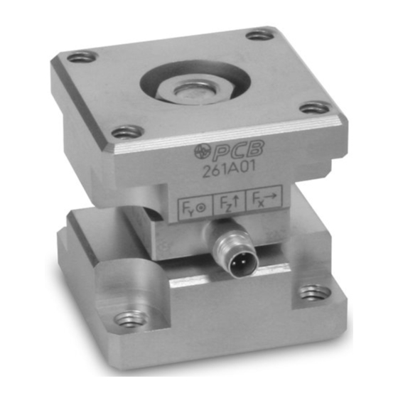
- Page 1 Model M261A01 3-Component ICP® Sensor Installation and Operating Manual For assistance with the operation of this product, contact PCB Piezotronics, Inc. Toll-free: 800-828-8840 24-hour SensorLine: 716-684-0001 Fax: 716-684-0987 E-mail: info@pcb.com Web: www.pcb.com...
- Page 2 Assistance is needed to safely operate equipment PCB Piezotronics is an ISO-9001 certified company whose Damage is visible or suspected calibration services are accredited by A2LA to ISO/IEC Equipment fails or malfunctions 17025, with full traceability to SI through N.I.S.T.
- Page 3 CAUTION Refers to hazards that could damage the instrument. NOTE Indicates tips, recommendations and important information. The notes simplify processes and contain additional information on particular operating steps. The following symbols may be found on the equipment described in this manual: This symbol on the unit indicates that high voltage may be present.
- Page 4 PCB工业监视和测量设备 - 中国RoHS2公布表 PCB Industrial Monitoring and Measuring Equipment - China RoHS 2 Disclosure Table 有害物质 镉 汞 铅 (Pb) 六价铬 (Cr(VI)) 多溴联苯 (PBB) 多溴二苯醚 (PBDE) 部件名称 (Hg) (Cd) 住房 PCB板 电气连接器 压电晶体 环氧 铁氟龙 电子 厚膜基板 电线 电缆 塑料 焊接...
- Page 5 Component Name Hazardous Substances Lead (Pb) Mercury (Hg) Cadmium (Cd) Chromium VI Polybrominated Polybrominated Compounds Biphenyls (PBB) Diphenyl Ethers (Cr(VI)) (PBDE) Housing PCB Board Electrical Connectors Piezoelectric Crystals Epoxy Teflon Electronics Thick Film Substrate Wires Cables Plastic Solder Copper Alloy/Brass This table is prepared in accordance with the provisions of SJ/T 11364.
-
Page 6: Table Of Contents
3-COMPONENT FORCE LINK OPERATION MANUAL Table of Contents Section Page Introduction Description Installation Operation Polarity Low Frequency Monitoring Discharge Time Constant Calibration Troubleshooting 10.0 Maintenance Figure Page 3-Component Force Link Axis Definition ICP® 3-Component Force Link Cable Strain Relief Characteristic Discharge Time Constant Curve Step Function Response MANUAL NUMBER:... -
Page 7: Introduction
1.0 INTRODUCTION If this should occur, refer to the service and repair document for proper information. PCB Piezotronics 3-component force link sensors are Measurements along the z-axis are proportional to designed to simultaneously measure dynamic and quasi- applied compression, tension, and impact forces. -
Page 8: Operation
3-COMPONENT FORCE LINK OPERATION MANUAL The condition of the mating surfaces can adversely 30 VDC, while the constant current required ranges affect the sensitivity of the sensor. It is essential that all from 2 to 20 surfaces be clean, rigid and perfectly flat to avoid erroneous data. -
Page 9: Discharge Time Constant
3-COMPONENT FORCE LINK OPERATION MANUAL features or zero "clamped" output often necessary in decay. Approximately five DTC intervals are needed repetitive, positive polarity pulse train applications. for a peak signal to naturally decay back to zero. If you wish to learn more about ICP® sensors, consult The rule of thumb for signal discharge, as outlined in PCB's General Signal Conditioning Guide (G-000lE), a Figure 4, is this: for the first 10% of the DTC, the signal... -
Page 10: Troubleshooting
3-COMPONENT FORCE LINK OPERATION MANUAL 9.0 TROUBLESHOOTING When a PCB signal conditioner with any of the 10.0 MAINTENANCE following indicators are used, tum the power on and observe the voltmeter ( or LED's) on the front panel. The sensor connector must be kept clean, especially if it is operating in a dusty and/or wet environment.
Need help?
Do you have a question about the M261A01 and is the answer not in the manual?
Questions and answers