
Summary of Contents for CELTIPOL CHV-320
- Page 1 TECHNICAL MANUAL 2022 CHV-320 HYDRAULIC SYSTEM FOR SPRAYING POLYURETHANE, POLYUREAS AND BI-COMPONENTS...
-
Page 2: Table Of Contents
CHV-320 TECHNICAL MANUAL 03-2022 Translation of the original manual TABLE OF CONTENTS: 1. GENERAL CONDITIONS........................4 2. SAFETY CONDITIONS........................... 5 3. APPLICATION SAFETY.......................... 6 4. SAFE HANDLING OF CHEMICAL PRODUCTS..................7 5. EQUIPMENT TECHNICAL SHEET......................8 6. OVERVIEW............................9 7. 2500 PUMPING UNIT........................12 8. - Page 3 CHV-320 TECHNICAL MANUAL 03-2022 Translation of the original manual 23. FAULT DETECTION IN THE APPLICATION:..................35 24. ELECTRICAL CONTROLS PANEL....................... 36 25. HOSE TRANSFORMER........................37 26. ELECTRICAL DIAGRAMS........................38 27. LIST OF COMPONENTS........................42 28. TRANSFER PUMPS C-M 16......................44 29.
-
Page 4: General Conditions
CHV-320 TECHNICAL MANUAL 03-2022 Translation of the original manual 1. GENERAL CONDITIONS. Before installing and starting up the Machine, read all the technical and safety documentation included in this manual carefully. It is important to pay particular attention to the information included here in order to become acquainted with handing and operating conditions of the Unit. -
Page 5: Safety Conditions
The first consideration to take into account is that during the design and project stage of the CHV-320 machine, the regulations in force regarding machine Safety and Prevention of Risk in the Work Place have been scrupulously respected. Therefore, we can firmly state that the machine is intrinsically safe. -
Page 6: Application Safety
CHV-320 TECHNICAL MANUAL 03-2022 Translation of the original manual 3. APPLICATION SAFETY. • It is advisable for personnel with a history of respiratory complaints to avoid exposure to all isocyanates. • Chemical products must be handled safely in accordance with manufacturer's recommendations. -
Page 7: Safe Handling Of Chemical Products
• Throughout the entire operation explained above, the area must be correctly ventilated. Safety personnel equipment: Celtipol recommends the following personnel safety equipment for operations with foaming (see table): •• Protective mask for airways. -
Page 8: Equipment Technical Sheet
CHV-320 TECHNICAL MANUAL 03-2022 Translation of the original manual 5. EQUIPMENT TECHNICAL SHEET. Technical characteristics: ..Power supply:..............Three-phase 220 V, 60Hz ..Preheater power:..................12,000w ..Transformer power:..................5,000w ..Electric engine power:..............5.3 H.P. - 4 Kw ... -
Page 9: Overview
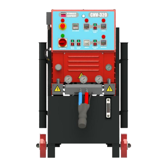
CHV-320 TECHNICAL MANUAL 03-2022 Translation of the original manual 6. OVERVIEW FRONT: 7052-1 7059 7057 2635 7053-4 7057 7168 7052-2 7056 7057 7074 7052-3 7058 7080 7053-3 7053-1 7054 7053-2 7043 7032 7045-1 2637 2640 7045-2 7049 1041 1041............Main wheels. - Page 10 CHV-320 TECHNICAL MANUAL 03-2022 Translation of the original manual REAR: 3220 2425 7039 2500 2612 7046 7046 2572 2612 2571 7225 7038 2344 7021 2100 2100...........Liquid filters unit. 7021............... 1/2” Plug. 2344........Hydraulic pressure pump. 7038............ Lubrication tank. 2425........Transfer pump brackets.
- Page 11 CHV-320 TECHNICAL MANUAL 03-2022 Translation of the original manual RIGHT SIDE: 2330 2633 2632 2630 2631 8110 2425 9110 2616 3223 2330............Air distributor. 2425......... Brackets for transfer pumps. 2616............Machine stand. 2630............. Machine casing. 2631..........Transformer housing. 2632............Electrical cabinet 2633.............Back cover.
-
Page 12: Pumping Unit
CHV-320 TECHNICAL MANUAL 03-2022 Translation of the original manual 7. 2500 PUMPING UNIT. 3220 7039 5543 5543 2509 2504 7063 2100 2100............Liquid filters. 2504............. Piston rod yoke. 2509............ Hexagonal pillar. 3220........Solenoid valve base plate. 5543..........M16 Self-locking nut. 7039............Solenoid valve... - Page 13 CHV-320 TECHNICAL MANUAL 03-2022 Translation of the original manual 3204 3210 3221 Ref. DESCRIPCIÓN 3203 2114 Sealing washer 1/2” 2421 O-ring Øin. 14x3 5733 3222 2503 Base pumping unit 3201 2508 Cylinder body 5740 2509 Hexagonal pillar (x4) 5735 3201...
- Page 14 CHV-320 TECHNICAL MANUAL 03-2022 Translation of the original manual 3207 3211 Ref. DESCRIPTION 3208 2203 Piston seal kit 2504 Piston rod yoke 3205 Piston-rod set 3209 3206 Lubr. pump gasket support 3207 Tip piston lubrication pump 3208 Lubrication pump guide 3211 3209 Lubr.
- Page 15 CHV-320 TECHNICAL MANUAL 03-2022 Translation of the original manual 7141 ISO pump unit Ref. DESCRIPTION 2112 Watertight washer 3/8” 3071 Lubrication elbow 1/8” 5802 Upper base 5820 5803 Nylon guide 5804 Seal stop ring 5830 5805 Cylinder body 5806 Piston rod...
- Page 16 CHV-320 TECHNICAL MANUAL 03-2022 Translation of the original manual 7142 POLI pump unit 5820 5830 Ref. DESCRIPTION 2112 Watertight washer 3/8” 5801 POLI packer bracket 5803 5802 Upper base 5803 Nylon guide 5801 5804 Seal stop ring 5805 Cylinder body...
-
Page 17: Liquid Filters Unit
CHV-320 TECHNICAL MANUAL 03-2022 Translation of the original manual 8. 2100 LIQUID FILTERS UNIT 2111 2109 2112 2108 2104 2107 2113 2108 2103 2106 2105 Ref. DESCRIPTION 2103 O-ring Øin. 30x2 SPARE PARTS KIT (2208) 2104 Filter body 2103 O-ring Øint 30x2... -
Page 18: Ends Of Stroke
CHV-320 TECHNICAL MANUAL 03-2022 Translation of the original manual 9. ENDS OF STROKE. 7112 2342 7115 7115 7112 Ref. DESCRIPTION 2342 Vertical bracket 7112 End of stroke bracket 7115 Limit switch... -
Page 19: Liquid Heater
CHV-320 TECHNICAL MANUAL 03-2022 Translation of the original manual 2570 LIQUID HEATER 7046 5243 2571 3076 5243 5243 2758 3021 7001 3057 7001 3056 3053 4762 2572 3074 Ref. DESCRIPCIÓN 2571 Left heater block (POLI) 2572 Right heater block (ISO) -
Page 20: Air Distributor
CHV-320 TECHNICAL MANUAL 03-2022 Translation of the original manual 2330 AIR DISTRIBUTOR. 2331-A 7034 7033 7086 1102 5243 7003 Ref. DESCRIPTION 1102 Air joint M1/2” - M1/2” 2331-A Air distribution block 5243 Plug 1 x 4” NPT 7003 Swift air connector female 3/8”... -
Page 21: Hose Outlet Unit
CHV-320 TECHNICAL MANUAL 03-2022 Translation of the original manual 2640 HOSE OUTLET UNIT 7045-2 7045-1 7001 7110 7086 7047 7003 7045-2 7001 7110 7011 2641 Ref. DESCRIPTION 2641 Hose outlet block 7001 Joint 3/8” NPT- G3/8” M 7003 Swift air connector female 3/8”... -
Page 22: Hose
CHV-320 TECHNICAL MANUAL 03-2022 Translation of the original manual HOSE 8110 MACHINE CONNECTION STRETCH 7005 2708 7008 2750 9117 2701 7004 7009 7223 2702 3007 9118 2707 7010 Ref. DESCRIPTION 2701 ISO line 2702 POLI line 2707 Hose wire 2708 Hose air conduit... - Page 23 CHV-320 TECHNICAL MANUAL 03-2022 Translation of the original manual 8130 HOSE FITTING 7121 7007 7006 3005 2751 7120 7007 3004 7006 Ref. DESCRIPTION 2751 Insulator separator 3004 ISO hose fitting 3005 POLI hose fitting 7006 Connector 5/16 hose - 1/2...
- Page 24 CHV-320 TECHNICAL MANUAL 03-2022 Translation of the original manual 8120 GUN CONNECTION STRETCH 3100-C 2703 3500 7006 2704 7007 7005 7004 2752 2707 2708 7005 4763 7133 Ref. DESCRIPTION 2020 7004 2020 Swift connector air gun 2703 ISO hose 7134...
-
Page 25: Hidraulic Pump
CHV-320 TECHNICAL MANUAL 03-2022 Translation of the original manual 14. HIDRAULIC PUMP 2793 2792 2794 2791 Pump pressure adjustment Electrical connections 2790 Boost 7162 pump 1104 7160 To hydraulic pressure gage Recirculation 7035 pump 7225 7030 2112 Washer 1/2” 2344... -
Page 26: Start-Up Sequence
CHV-320 TECHNICAL MANUAL 03-2022 Translation of the original manual START-UP SEQUENCE. 1. Install the machine completely fixed and stable. 2. Electrical connection of the unit. Ensure that the electrical connection is correct and that the line is suitably shielded (magnetothermal and differential shielding). Check the correct connection of the phases. -
Page 27: Selecting Work Temperature
SELECTING WORK CYCLE. Celtipol machines can be fitted, if required by the customer, with a cycle counter with preselect and with the possibility of blocking when the machine reaches the end of the cycles indicated. -
Page 28: Daily Stop Sequence
9. Close the stopcock taps for products on the gun and pull the trigger 2 or 3 times. 10. Close the air stopcock on the gun. 11. Dismantle the side and front housings of the gun for cleaning. Lubricate with Celtipol grease 12. -
Page 29: Extended Stop Sequence (Over One Month)
Re-add the spray until all the solvent has been bled from the system and only the plasticizer comes out of the side blocks Apply a thick layer of Celtipol grease to each side of the front housing of the gun. Once again, place the side blocks on the front housing of the gun ... -
Page 30: System Maintenance
CHV-320 TECHNICAL MANUAL 03-2022 Translation of the original manual SYSTEM MAINTENANCE. Lubricate the Piston rods when stopping the machine with D.O.P. (Daily) 17• Clean and refill the gun with white lithium grease or petroleum jelly (daily). Clean filters on the product input with ethyl-glycol (weekly). - Page 31 CHV-320 TECHNICAL MANUAL 03-2022 Translation of the original manual Gun: Ensure that the product tap is fully open. Check the cleanliness of the front hole on the mixing chamber. Check for the extent of cleanliness in the filter grille.
-
Page 32: Locating Incidents
Translation of the original manual LOCATING INCIDENTS. The CHV-320 machine has been designed and built to withstand severe work conditions with a high degree of reliability, on the condition that it is used and maintained in the appropriate manner. See below for information on possible incidents that may cause problems preventing continuing to operate with the Machine. - Page 33 CHV-320 TECHNICAL MANUAL 03-2022 Translation of the original manual 5. Unbalanced pressures: Decompensation of pressures occurs when an obstruction in the hose or in the gun prevents one of the components to be freely released through the gun chamber when projected or when a problem in the pumping system prevents one of the components from being able to reach the gun in the required amount.
- Page 34 CHV-320 TECHNICAL MANUAL 03-2022 Translation of the original manual 7. Failure in the ends of stroke in change of direction. The dosing pump system has two limit switches to change the direction of the pumping unit. If one of them fails, the pump unit will lock in position near where the end of stroke has failed.
-
Page 35: Fault Detection In The Application
CHV-320 TECHNICAL MANUAL 03-2022 Translation of the original manual FAULT DETECTION IN THE APPLICATION: The simplest way to objectively detect if there are faults in the application is to observe the spraying, which is affected by the following parameters: Temperature: A material that is too hot will produce separation in the fan. A material that is too cold will produce a ripple effect. -
Page 36: Electrical Controls Panel
CHV-320 TECHNICAL MANUAL 03-2022 Translation of the original manual ELECTRICAL CONTROLS PANEL. 7203 7204-1 9012 7206 7209 7219 7207 7208 7211 7204-2 7210 7212 7215 7219 7221 7213 7203 ...General magnetothermal 3x32A 7204-1....General contactor K1 7209 Solenoid valve relay R7 7204-2.....Motor contactor K2... -
Page 37: Hose Transformer
CHV-320 TECHNICAL MANUAL 03-2022 Translation of the original manual HOSE TRANSFORMER. 7042 7222 5000 VA transformer connection example Electrical connections for different lengths of heated hoses 7222 Ammeter transformer. 7042 Hose transformer... -
Page 38: Electrical Diagrams
CHV-320 TECHNICAL MANUAL 03-2022 Translation of the original manual ELECTRICAL DIAGRAMS. - Page 39 CHV-320 TECHNICAL MANUAL 03-2022 Translation of the original manual...
- Page 40 CHV-320 TECHNICAL MANUAL 03-2022 Translation of the original manual...
- Page 41 CHV-320 TECHNICAL MANUAL 03-2022 Translation of the original manual...
-
Page 42: List Of Components
CHV-320 TECHNICAL MANUAL 03-2022 Translation of the original manual LIST OF COMPONENTS 1041 Main wheels ............p9 2758 Thermostat............p21 1102 Air joint M1/2” - M1/2” ........p22 2790 Suction pump sleeve...........p27 1104 Joint M-M 1/4”NPT 1/4”Gas.......p27 2791 Bost pump sleeve..........p27 2020 Swift connector air gun........p26... - Page 43 CHV-320 TECHNICAL MANUAL 03-2022 Translation of the original manual 5532 Screw M12x70............ p13 7053-1 Hydraulic central start-up pushbutton....p9 5732 Wiper seal............p13 7053-2 Hidraulic cylinder start-up pushbutton..... p9 5733 Rod Seal.............. p13 7053-3 Hose start-up pushbutton......... p9 5735 O-ring Øin. 60x3.5..........p13 7053-4 Heater start-up pushbutton......
-
Page 44: Transfer Pumps C-M 16
CHV-320 TECHNICAL MANUAL 03-2022 Translation of the original manual TRANSFER PUMPS C-M 16 Technical characteristics of the equipment Air pressure:......................101lb/in² Air consumption:....................53gal/min. Maximum product outlet pressure:..............290lb/in² Pressure ratio:......................2,8 : 1 Outflow:....................... 8gal/min. - Page 45 CHV-320 TECHNICAL MANUAL 03-2022 Translation of the original manual Safety in the use of the equipment • It is advisable for personnel with a history of respiratory complaints to avoid exposure to all isocyanates. • Chemical products must be handled safely in accordance with manufacturer's recommendations.
- Page 46 CHV-320 TECHNICAL MANUAL 03-2022 Translation of the original manual Start up Insert the pump through the mouth of the drum Screw the clamp to the drum (5074) and tighten the seal (It is recommended to apply grease to both threads and gasket).
- Page 47 CHV-320 TECHNICAL MANUAL 03-2022 Translation of the original manual Kit 5006: Kit 5072: 5059 5028 5072 5060 5059 5006 5069 Kit 5075: 5827 5826 5053 5054 Kit 5071: 5075 5051 5071 5034 5036 5052...
- Page 48 CHV-320 TECHNICAL MANUAL 03-2022 Translation of the original manual 5001 5030 5029 5005 5027 5002 5066 5006 5003 5025 5024 5049 5047 5065 5045 5075 5056 5050 5068 5048 5046 5055 5057 5011 5013 5067 5072 5019 5007 5058 5005...
- Page 49 CHV-320 TECHNICAL MANUAL 03-2022 Translation of the original manual Transfer pump part list C-M 16 DESCRIPTION Kit.5006 Gaskets and felts 2109 Joint M 1/2” – M 1 1/16” SAE DESCRIPTION 2918 Product outlet hose 5028 Felts 2919 Air inlet hose...
-
Page 50: Commercial Guarantee
2. This guarantee does not cover or pay for damages resulting from changes or adjustments that may be made to the product, without the prior written consent of CELTIPOL in order to comply with safety or technical standards, national or local, in countries other than those for which the product has been designed and manufactured. - Page 51 Failure to use the product for purposes other than those for which it is designed or failure to comply with CELTIPOL's instructions for use and maintenance. Installation or use of the product in a manner that does not comply with the technical or safety regulations of the country where used.
-
Page 52: Ce Declaration
CHV-320 TECHNICAL MANUAL 03-2022 Translation of the original manual CE DECLARATION. - Page 53 CHV-320 TECHNICAL MANUAL 03-2022 Translation of the original manual...
Need help?
Do you have a question about the CHV-320 and is the answer not in the manual?
Questions and answers