Table of Contents
Advertisement
Quick Links
Meraki MG41 and MG41E Installation
This document describes how to install and set up the MG41 LTE gateway. Additional
reference documents are available online at: www.meraki.com/library/products.
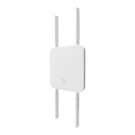
MG41-HW Overview
The Meraki MG41-HW (model: MG41-HW, MG41E-HW) is an enterprise LTE gateway
designed for distributed deployments that require remote administration. It is ideal for
network administrators who demand both ease of deployment and a state-of-the-art feature
set. This appliance provides the following new features:
•
Support for 2 LAN connections (1for 802.3at support)
•
Wall screws and anchors for mounting drywall surface, either vertically or
horizontally
MG41-HW Operational Temperature: -40
Package Contents
In addition to the MG41-HW, the following are provided.
Guide
F to 140
F (-40
o
o
o
C to 60
C)
o
Advertisement
Table of Contents

Related Manuals for Meraki MG41

Summary of Contents for Meraki MG41
- Page 1 Meraki MG41 and MG41E Installation Guide This document describes how to install and set up the MG41 LTE gateway. Additional reference documents are available online at: www.meraki.com/library/products. MG41-HW Overview The Meraki MG41-HW (model: MG41-HW, MG41E-HW) is an enterprise LTE gateway designed for distributed deployments that require remote administration.
- Page 2 The MG41-HW front panel Ports and Status Indicators The MG41-HW uses a single LED to inform the user of the device's status. Function LED Status Meaning Power Up/Boot Solid Power is applied Orange Connecting Rainbow Device in process of connecting to the Meraki Dashboard...
- Page 3 Power input Designed for use only with the unit’s power supply. Antenna ports Four RP-SMA ports for dipole antennas (antennas included) The MG41-HW input panel Restore button Insert a paper clip if a reset is required. • A brief, momentary press: To delete a downloaded configuration and reboot.
-
Page 4: Mounting Hardware
Mounting hardware The supplied wall screws and anchors allow you to mount the appliance on a drywall surface, either vertically or horizontally. The distance between the holes you drill should be 93 mm. • For mounting on drywall, use a ¼-in drill bit, then insert the plastic and screw assemblies. •... - Page 5 Mount Option: B Attaching external antennas (MG41E only):...
- Page 6 Mounting the device:...
-
Page 7: Connecting To The Wan
Power Powering the MG41 and MG41E in an outdoor deployment will require the use of the POE injector. For outdoor installation using the approved POE injector the installer must place the... -
Page 8: Additional Settings
Setting up a DHCP IP address By default all MG devices are configured to DHCP from upstream WAN / ISP servers. Simply plug one of the MG's WAN / Internet ports into your upstream circuit and wait a few minutes for the unit to negotiate a DHCP address. -
Page 9: Fcc Compliance Statement
This device may not cause harmful interference, and (2) this device must accept any interference received, including interference that may cause undesired operation. Party issuing Supplier’s Declaration of Conformity Cisco Meraki 500 Terry A. Francois Blvd. San Francisco, CA 94158 compliance@meraki.com... -
Page 10: Industry Canada Statement
This equipment requires professional installation. Industry Canada Statement The MG41-HW, MG41E-HW comply with license-exempt RSSs of the Industry Canada Rules. Operation is subject to the following two conditions: (1) This device may not cause harmful interference, and (2) this device must accept any interference received, including interference that may cause undesired operation. - Page 11 for use with this device. Innovation, Sciences et Développement économique Canada a approuvé l'utilisation de ce transmetteur radio avec les types d'antenne énumérés ci-dessous, le gain maximal admissible étant indiqué. Les types d'antennes non inclus dans cette liste qui ont un gain supérieur au gain maximal indiqué...
- Page 12 Antenna Information Antenna Ant. Port Brand Model Name Type Connector Remark Gain (dBi) 1 1, Primary #0 CISCO N/A I-PEX PIFA 2 2, Primary #1 CISCO N/A I-PEX PIFA Note 1 Internal 3 3, Secondary #0 CISCO N/A I-PEX PIFA 4 4, Secondary #1 CISCO N/A I-PEX PIFA Antenna Set Ant. Port Brand Model Name...
- Page 13 Note1: Set Band Port Antenna Gain (dBi) Remark 1, Primary #0 TX, RX 2.81 WCDMA Band 2 1TX/2RX 3, Secondary #0 RX 2.03 1, Primary #0 TX, RX 2.48 WCDMA Band 4 1TX/2RX 3, Secondary #0 RX 2.59 1, Primary #0 TX, RX 1.04 WCDMA Band 5 1TX/2RX 3, Secondary #0 RX 0.98 1, Primary #0 TX, RX 2.81 2, Primary #1 RX 2.96 1TX/2RX: Port 1 (TX) / Port 1, 3 (RX) LTE Band 2 3, Secondary #0 RX 2.03 1TX/4RX: Port 1 (TX) / Port 1 ~ 4 (RX) 4, Secondary #1 RX 2.09 1, Primary #0 TX, RX...
- Page 14 Set Band Port Antenna Gain (dBi) Remark 2, Primary #1 RX 1.50 1TX/4RX: Port 1 (TX) / Port 1 ~ 4 (RX) 3, Secondary #0 RX 2.86 4, Secondary #1 RX 2.09...
- Page 15 Antenna Cable True Gain Loss Gain Set Band Port Remark (dBi) (dB) (dBi) 1, Primary #0 TX, RX 1.6 0.6 1.0 WCDMA 1TX/2RX Band 2 4, Secondary #0 RX Down 2.40 0.6 1.8 1, Primary #0 TX, RX 2.10 0.6 1.5 WCDMA 1TX/2RX Band 4 4, Secondary #0 RX Down 2.00 0.6 1.4 1, Primary #0 TX, RX 1.50 0.6 0.9 WCDMA 1TX/2RX...
- Page 16 Antenna Cable True Gain Loss Gain Set Band Port Remark (dBi) (dB) (dBi) 1, Primary #0 TX, RX 2.1 0.6 1.5 2, Secondary #1 RX 1.80 0.7 1.1 1TX/2RX: Port 1 (TX) / Port 1, 4 (RX) LTE Band 66 3, Primary #1 RX 1.50 0.9 0.6 Down 1TX/4RX: Port 1 (TX) / Port 1 ~ 4 (RX) 4, Secondary #0 RX Down 2.00 0.6 1.4 Antenna Cable True Gain Loss Gain Set Band Port...
- Page 17 Antenna Cable True Gain Loss Gain Set Band Port Remark (dBi) (dB) (dBi) 2, Secondary #1 RX 8.2 0.7 7.5 1TX/4RX: Port 3 (TX) / Port 1 ~ 4 (RX) 3, Primary #1 TX, RX Down 7.8 0.9 6.9 4, Secondary #0 RX Down 8.2 0.6 7.6 Antenna Cable True Gain Loss Gain Set Band Port Remark (dBi) (dB) (dBi) 1, Primary #0 TX, RX 7.2...
- Page 18 Set Band Port Antenna Gain (dBi) Remark 1, Primary #0 TX, RX 1.1 0.6 0.5 LTE Band 14 1TX/2RX 4, Secondary #0 RX Down 0.6 1.4 2.00 1, Primary #0 TX, RX 6.10 0.6 5.5 LTE Band 14 1TX/2RX 4, Secondary #0 RX Down 6.50 0.6 5.9 Note: The above information was declared by manufacturer. For conducted test, only the highest antenna gain has been tested and recorded in the test report. For radiated test, set 1 ~ set 3 antenna has been tested and recorded in the test report. Antenna Set Ant. Port Brand Model Name Type Connector Remark Gain (dBi) 1 1, Primary #0 CISCO N/A...
- Page 19 Antenna Set Ant. Port Brand Model Name Type Connector Remark Gain (dBi) 1 1, Primary #0 CISCO N/A I-PEX PIFA 2 2, Primary #1 CISCO N/A I-PEX PIFA Note 1 Internal 3 3, Secondary #0 CISCO N/A I-PEX PIFA 4 4, Secondary #1 CISCO N/A I-PEX PIFA Antenna Set Ant. Port Brand Model Name...
- Page 20 Antenna Set Ant. Port Brand Model Name Type Connector Remark Gain (dBi) 1 1, Primary #0 CISCO N/A I-PEX PIFA 2 2, Primary #1 CISCO N/A I-PEX PIFA Note 1 Internal 3 3, Secondary #0 CISCO N/A I-PEX PIFA 4 4, Secondary #1 CISCO N/A I-PEX PIFA Antenna Set Ant. Port Brand Model Name...
Need help?
Do you have a question about the MG41 and is the answer not in the manual?
Questions and answers