Table of Contents
Advertisement
Quick Links
Advertisement
Table of Contents

Subscribe to Our Youtube Channel
Summary of Contents for SWF AQUAFLOW AQF5500
- Page 1 Solar Pumping Inverter User’s Manual...
- Page 2 Preface Thank you very much for using AQUAFLOW Series Solar Pumping Inverter. In order to give full play to the product performance and guarantee the safety of user and equipment, before installation and use, please carefully read the manual. In order to facilitate daily inspection and maintenance of inverter and understand abnormal reason and solutions, please keep the instruction properly.
-
Page 3: Table Of Contents
Operation Instruction of AQUAFLOW Series Solar Pumping Inverter Precautions Contents Precautions ..........................II Chapter I Product Introduction .................... 1 1.1 Introduction to Solar Pumping System ................1 1.2 Product Characteristics ......................2 1.3 Inverter Specification ......................3 Chapter II Installation and Wiring ..................7 2.1 Procurement Inspection ....................... -
Page 4: Precautions
Operation Instruction of AQUAFLOW Series Solar Pumping Inverter Precautions Precautions The safe operation of the product is subject to correct transportation, installation, operation, and maintenance. Before conducting these tasks, please pay attention to relevant safety instructions. The warnings related to safety in the manual are listed as follows: Grounding Wire of Equipment AC Value DC Value... - Page 5 Operation Instruction of AQUAFLOW Series Solar Pumping Inverter Precautions 2. Try to install it in the indoor place with ventilation opening or air interchanger. It is forbidden to install it directly under sunshine. 3. During installation, do not discard residue of drill hole into inverter cooling find or fan, which may affect heat dissipation.
- Page 6 Operation Instruction of AQUAFLOW Series Solar Pumping Inverter Precautions Warning 1. Before the first operation, please adjust some control parameters according to operation instruction. Do not alter the control parameters of inverter at random, or else it may damage the equipment. 2.
-
Page 7: Chapter I Product Introduction
Operation Instruction of AQUAFLOW Series Solar Pumping Inverter Product Introduction Chapter I Product Introduction 1.1 Introduction to Solar Pumping System Solar Pumping System is widely applied in domestic water, agricultural irrigation, forestry watering, desert control, grassland animal husbandry, island water supply, water treatment project, etc. -
Page 8: Product Characteristics
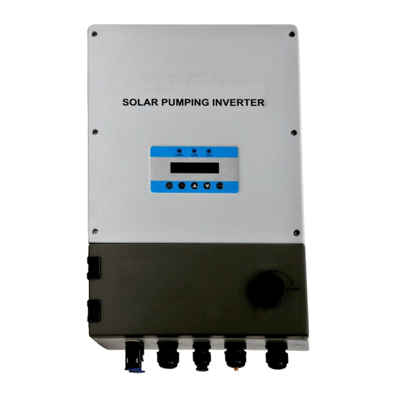
Operation Instruction of AQUAFLOW Series Solar Pumping Inverter Product Introduction 1.2 Product Characteristics On the basis of many-year research, development, and experiment, the pumping inverter (Figure 1-2) independently developed and produced by our company has the following advantages: u Use independently-developed dynamic VI MPPT (Maximum Power Point Tracking) control method. -
Page 9: Inverter Specification
Operation Instruction of AQUAFLOW Series Solar Pumping Inverter Product Introduction overvoltage/undervoltage protection, motor overload protection, inverter overload protection, output side phase loss protection, inverter module overheat protection, grounding short circuit protection, and underload (anti-dry pumping) protection. u The main circuit uses power module (PIM), and the reliability is higher. u The small-power model uses completely-new aluminum shell, LCD display operation panel, and directly-insert connection terminal. - Page 10 Operation Instruction of AQUAFLOW Series Solar Pumping Inverter Product Introduction Figure 1-3 Introduction to Product Nameplate and Model Identification Introduction Product Series Rated Power (W) of Motor Output Voltage (L: 220V None:380V) A: with electric supply function None: without electric supply function Warning: do not rip out product nameplate label.
- Page 11 Operation Instruction of AQUAFLOW Series Solar Pumping Inverter Product Introduction Max. Recommen Start Rated Max.AC Output ded MPP DC input Rated output voltage Model output output frequency voltage voltage voltage Vac power W current A (Vdc) (Vdc) (Vdc) AQUAFLOW 100-400 0-50/60 3PH 220V 550-L...
- Page 12 Operation Instruction of AQUAFLOW Series Solar Pumping Inverter Product Introduction AQUAFLOW 500-680 4000 0-50/60 3PH 380V 4000 AQUAFLOW 500-680 5500 0-50/60 3PH 380V 5500 AQUAFLOW 500-680 7500 0-50/60 3PH 380V 7500 AQUAFLOW 500-680 9200 0-50/60 3PH 380V 9200 AQUAFLOW 11K 500-680 11000 0-50/60...
- Page 13 Operation Instruction of AQUAFLOW Series Solar Pumping Inverter Product Introduction 11K-A AQUAFLOW 500-680 13000 0-50/60 3PH 380V 13K-A AQUAFLOW 500-680 15000 0-50/60 3PH 380V 15K-A AQUAFLOW 500-680 18500 0-50/60 3PH 380V 18K5-A AQUAFLOW 500-680 22000 0-50/60 3PH 380V 22K-A Warning: please select appropriate model according to solar cell array and motor load. Warning: The input power in the above table refers to multi-channel total input power.
-
Page 14: Chapter Ii Installation And Wiring
Operation Instruction of AQUAFLOW Series Solar Pumping Inverter Installation and Wiring Chapter II Installation and Wiring 2.1 Procurement Inspection Our company has strict quality assurance system in aspects of product manufacturing, packaging, etc. In case of abnormal condition, please contact with our company’s product dealer, or contact with our company’s technical service center. - Page 15 Operation Instruction of AQUAFLOW Series Solar Pumping Inverter Installation and Wiring Product Specification Parameter: Appearance and installation dimension (mm) Model Weight Kg AQUAFLOW 550-L AQUAFLOW 750-L AQUAFLOW 1100-L AQUAFLOW 1500-L AQUAFLOW 2200-L AQUAFLOW 550-LA AQUAFLOW 750-LA AQUAFLOW 1100-LA AQUAFLOW 1500-LA AQUAFLOW 2200-LA AQUAFLOW 3000 AQUAFLOW 4000...
-
Page 16: Installation Diagram
Operation Instruction of AQUAFLOW Series Solar Pumping Inverter Installation and Wiring Warning: most models of AQUAFLOW series are hanging installation. Guarantee that the installation backboard can bear the weight of inverter. 2.3 Installation Diagram Figure 2-2 Installation Dimension Diagram of AQUAFLOW 550 to 2200 Figure 2-3 Installation Dimension Diagram of AQUAFLOW 3000 to 5500... - Page 17 Operation Instruction of AQUAFLOW Series Solar Pumping Inverter Installation and Wiring Figure 2-4 Installation Dimension Diagram of AQUAFLOW 7500 to 13K Figure 2-5 Installation Dimension Diagram of AQUAFLOW 15K to 22K...
- Page 18 Operation Instruction of AQUAFLOW Series Solar Pumping Inverter Installation and Wiring Figure 2-6 Install Safety Nut Figure 2-7 Correct Arrangement Diagram of Inverter...
-
Page 19: Wiring Diagram
Operation Instruction of AQUAFLOW Series Solar Pumping Inverter Installation and Wiring 2.4 Wiring Diagram 2.4.1 Wiring Diagram of AQUAFLOW 550-2200 AC Output Terminal PV Input Terminal AC Input Terminal Water Level Terminal Figure 2-8 Wiring Terminal Figure 2-9 AQUAFLOW 550-L to 2200-L Wiring Diagram... - Page 20 Operation Instruction of AQUAFLOW Series Solar Pumping Inverter Installation and Wiring Figure 2-10 AQUAFLOW 550-LA to 2200-LA Wiring Diagram 2.4.2 3000 to 5500 Wiring Diagram of AQUAFLOW Figure 2-11 AQUAFLOW 3000 to 5500 Wiring Terminal...
- Page 21 Operation Instruction of AQUAFLOW Series Solar Pumping Inverter Installation and Wiring Figure 2-12 AQUAFLOW 3000 to 5500 Wiring Diagram Figure 2-13 AQUAFLOW 3000-A to 5500-A Wiring Diagram...
- Page 22 Operation Instruction of AQUAFLOW Series Solar Pumping Inverter Installation and Wiring 2.4.3 7500 to 13K Wiring Diagram of AQUAFLOW Figure 2-14 AQUAFLOW 7.5K to 13K Wiring Terminal Figure 2-15 AQUAFLOW 7.5K to 13K Wiring Diagram...
- Page 23 Operation Instruction of AQUAFLOW Series Solar Pumping Inverter Installation and Wiring Figure 2-16 AQUAFLOW 7.5K-A to 13K-A Wiring Diagram 2.4.4 Wiring Diagram of AQUAFLOW 15K to 22K Figure 2-17 AQUAFLOW 15K to 22K Wiring Terminal...
- Page 24 Operation Instruction of AQUAFLOW Series Solar Pumping Inverter Installation and Wiring Figure 2-18 AQUAFLOW 15K to 22K Wiring Diagram Figure 2-19 AQUAFLOW 15K- A to 22K- A Wiring Diagram Use key to open the lower cover of crate. There is DC switch, water level sensor connection terminal, GPRS (optional), and AC output terminal.
- Page 25 Operation Instruction of AQUAFLOW Series Solar Pumping Inverter Installation and Wiring Analog Output Analog Output Relay 1 Output Relay 2 Output Figure 2-20 A/O Terminal Diagram Figure 2-21 I/O Terminal Diagram...
- Page 26 Operation Instruction of AQUAFLOW Series Solar Pumping Inverter Installation and Wiring Terminal Introduction Socket Terminal Introduction Wiring Introduction Connect with the positive pole of solar array Input Connect with the negative pole of solar array Connect with protective ground wire Connect with motor U phase Output Connect with motor V phase...
- Page 27 Operation Instruction of AQUAFLOW Series Solar Pumping Inverter Installation and Wiring 2.4.4 Recommended Diameter of Wire (mm Recommende Output length≤ length≤ length≤ length≤ length≤ length≤ length≤ model voltage(V) d output 120m 150m 180m 210m current(A) AQUAFLOW 1HP 230V 0.75 550-L AQUAFLOW 3HP 220V 0.75...
-
Page 28: Assemble Dc Connector
Operation Instruction of AQUAFLOW Series Solar Pumping Inverter Installation and Wiring AQUAFLOW 3HP 380V AQUAFLOW 3HP 380V AQUAFLOW 3HP 380V 18K5 AQUAFLOW 3HP 380V Units: mm Notice: the environment temperature of the above recommended wire dimension is ≤50°C. Notice: large-power wall-mounted model uses multiple-channel DC input. The dimension of DC wire of each channel shall be selected according to the above table. - Page 29 Operation Instruction of AQUAFLOW Series Solar Pumping Inverter Installation and Wiring Figure 2-23 2.5.3 Insert contact cable assembly into back of the male and female connector. tight nuts according to the opposite direction. Now wiring is finished. Figure 2-24 2.5.4 The PV importation that will assemble a good DC conjunction machine to make an effort to insert Inverters carries and link OK after hearing the sound of "click".
-
Page 30: Introduction To The Wiring Of Water Level Sensor
Operation Instruction of AQUAFLOW Series Solar Pumping Inverter Installation and Wiring 2.6 Introduction to the Wiring of Water Level Sensor DC Switch Connect S2 and COM Water Level Sensor 2 Impounding Reservoir Connect Three-Phase Output Connect S4 and COM Water Pump Water Level Sensor 1 Water Well Figure 2-25 Wiring Diagram of Water Level Detector... -
Page 31: Chapter Iii Operation Control
Operation Instruction of AQUAFLOW Series Solar Pumping Inverter Operation Control Chapter III Operation Control 3.1 Panel Layout and Introduction Solar Pumping Inverter uses LCD operation panel. The operation panel is shown in the figure, including 3 LED lights,LCD display and 5 keys. Figure 3-1 Keyboard Layout and Each Part Name Indicator and Key Name... -
Page 32: Panel Operation Method
Operation Instruction of AQUAFLOW Series Solar Pumping Inverter Operation Control Indicator and Key Name Function Introduction 1. Press for a short time to enter programming mode. After altering parameter, “press for a short time” to Confirm/Progra confirm the alteration mming Key 2. -
Page 33: Work Mode
Operation Instruction of AQUAFLOW Series Solar Pumping Inverter Operation Control ↓ Input voltage of the inverter Represent 542.3V ↓ Output voltage of the inverter Represent 379V ↓ Output current of the inverter Represent 11.1A ↓ The relative value of rated power Represent 79.1% ↓ Output frequency of the inverter Represent 50.00Hz 3.3 Work Mode The inverter includes three work modes: keyboard manual mode, fully-automatic work mode, GPRS work mode (optional). -
Page 34: Introduction To The Procedure Of Wiring And Debugging
Operation Instruction of AQUAFLOW Series Solar Pumping Inverter Operation Control cellphone number. Send messages to set startup, shutdown, parameter inquiry, etc. Warning: do not change menu S00 parameters. The default mode is fully-automatic work mode. 3.4 Introduction to the Procedure of Wiring and Debugging 3.4.1 Procedure of Power Supply Debugging of Solar Cell 1. - Page 35 Operation Instruction of AQUAFLOW Series Solar Pumping Inverter Operation Control 2. Conduct parameter setting for the motor (a) Setting S00.01=0. Command code channel is keyboard manual mode instruction. (b) Set water pump nameplate parameters: S02.01 motor rated power value; S02.02 motor rated power value;...
- Page 36 Operation Instruction of AQUAFLOW Series Solar Pumping Inverter Operation Control Operation Description Display ↓ Return the main parameter modification interface for long press 2s Represent S00 parameter group ↓ Long press OK for 2s to return to the initial status Represent Working freq. 50.00Hz ↓ Long press ON/OFF key for 2s to stop the inverter. Represent Set freq. 50.00Hz ↓ Enter the main parameter modification interface for long press 2s Represent S00 parameter group ↓ Press the UP key to S02 group Represent S02 parameter group ↓...
- Page 37 Operation Instruction of AQUAFLOW Series Solar Pumping Inverter Operation Control Operation Description Display Edited the rated and current of the pump(it will write in pump) ↓ e.g.11.3A Represent 11.3A Press to save the parameter value and return to the branch ↓ menu Represent S00 parameter group Long press OK for 2s to ↓ return to the main menu Represent S02 parameter group Press DOWN key to S00 ↓...
- Page 38 Operation Instruction of AQUAFLOW Series Solar Pumping Inverter Operation Control Operation Description Display Long press OK for 2s to initial return to the status. ↓ Represent 50.00Hz Turn off the DC switch, waiting the LCD display off, then turn on the DC switch, the inverter will auto-start to drive pump(5.5kW) 3. After finishing all parameter settings, turn off Q2 of DC switch. After display screen is OFF for 5 minutes, turn on AC output.
- Page 39 Operation Instruction of AQUAFLOW Series Solar Pumping Inverter Operation Control Power grid Solar cell panel Water level switch DC switch Impounding Reservoir 2. Turn off Q2 switch, then turn on Q1 switch. 3. After power-on, adjust motor parameter according to Item 2 of Article 3.4.1. 4.
- Page 40 Operation Instruction of AQUAFLOW Series Solar Pumping Inverter Operation Control Name Scope Introduction Factory Value 0: keyboard operation code channel (LED is off) Operation code 1: terminal operation code channel S00.01 channel (LED flickers) 2: communication operation code channel (LED is bright) Rated power of Model S02.01...
-
Page 41: Chapter Iv: Failure Diagnosis
Operation Instruction of AQUAFLOW Series Solar Pumping Inverter Operation Control Chapter IV: Failure Diagnosis 4.1 Explanation and Solution for Fault Code AQUAFLOW series solar pumping inverter has complete protection. When system suffers failure, the inverter will take protective measures: the general protective measures are to stop the output of drive signal of motor and forbid to re-start within a certain period. - Page 42 Operation Instruction of AQUAFLOW Series Solar Pumping Inverter Operation Control Output short circuit Check wiring Module IGBT shortcut or grounding Seek services from overcurrent Module damage manufacturer Air flue is blocked Module Environment Clean air flue or improve Inv Overtemp over-temperatur temperature is too ventilation...
-
Page 43: Chapter V Maintenance
Chapter V Maintenance 5.1 Daily Inspection and Maintenance Affected by environment temperature, humidity, vibration, and inverter internal component aging, the inverter may suffer some potential problems during operation. In order to stably operate the inverter for a long term, conduct periodical inspection once each year. 5.1.1 Requirements of Inspection and Maintenance 1. -
Page 44: Inspection And Replacement Of Quick-Wear Parts
5.2 Inspection and Replacement of Quick-wear Parts 5.2.1 Filter Capacitor The pulsating current of main loop will affect the performance of filter capacitor of aluminium electrolysis. The affected degree and environment temperature are related to service environment. Under normal conditions, the inverter shall change electrolytic capacitor once every 10 years. When electrolyte of electrolytic capacitor leaks, safety valve emits, or capacitance expands, replace it immediately. -
Page 45: Quality Assurance
Quality Assurance Warranty Policy: Warranty period: Our company provides series solar pumping inverter with warranty period of 24 months. The systematic components provided by our company have 12-month warranty period. Starting date of warranty period: the date when user gets goods from our dealer. Warranty proof: product series number and local dealer’s shipment invoice. - Page 46 If claim exceeds the power quoted in warranty principle,our company shall not undertake legal responsibilities, including the following conditions: claim compensation due to direct or indirect damaged caused by defective equipment; claim compensation due to the damage caused by removal and installation;...
-
Page 47: Warranty Card
Warranty Card Contact Client Name Person Client Address Contact Tel. Product Procurement Specification Date Warranty Date Equipment Code (since production date) Distribution Unit (Seal) Packing List (1) Main engine quantity: One set (2) Instruction book (including warranty card) quantity: one (3) Patch plug of positive pole of solar cell array quantity: one (4) Patch plug of negative pole of solar cell array quantity: one (5) Water level sensor quantity: one (optional)
Need help?
Do you have a question about the AQUAFLOW AQF5500 and is the answer not in the manual?
Questions and answers