
Subscribe to Our Youtube Channel
Related Manuals for LD U 500 CS4


Summary of Contents for LD U 500 CS4
- Page 1 USER´S MANUAL BEDIENUNGSANLEITUNG MANUEL D`UTILISATION MANUAL DE USUARIO INSTRUKCJA OBSŁUGI MANUALE D‘ USO U 500 CS4 4 CHANNEL WIRELESS CONFERENCE SYSTEM LDU500CS4 SERIES...
-
Page 2: Table Of Contents
CONTENTS / INHALTSVERZEICHNIS / CONTENU / CONTENIDO / TREŚĆ / CONTENUTO ENGLISH ESPAÑOL PREVENTIVE MEASURES MEDIDAS DE SEGURIDAD 45-46 INTRODUCTION INTRODUCCIÓN 46-47 CONNECTIONS, CONTROLS AND INDICATORS CONEXIONES, CONTROLES E INDICADORES RECEIVER RECEPTOR 47-48 MICROPHONE STATION UNIDAD DE CONFERENCIA OPERATION 8-14 OPERACIÓN 50-56 ERROR DETECTION... -
Page 3: English
YOU‘VE MADE THE RIGHT CHOICE! We have designed this product to operate reliably over many years. LD Systems stands for this with its name and many years of experience as a manufacturer of high-quality audio products. Please read this User‘s Manual carefully, so that you can begin making optimum use of your LD Systems product quickly. -
Page 4: Introduction
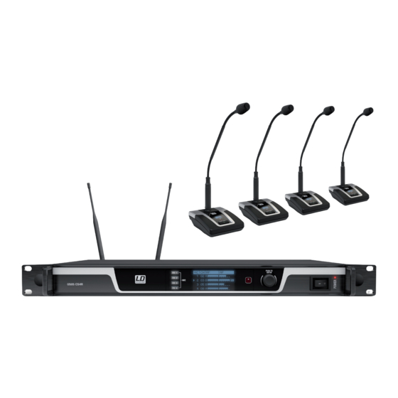
- Consult the dealer or an experienced radio/TV technician for help. INTRODUCTION LD Systems U500 CS 4 - 4-channel wireless conference system The U500 microphone stations feature a gooseneck condenser microphone with a hyper cardioid pattern. The heavy table base has a ®... -
Page 5: Connections, Controls And Indicators
LDU50xCS4: Quad receiver plus 4 x microphone stations with gooseneck microphone, power supply, 2 x BNC antennae, 8 x AA batteries, rack kit, Mini- DIN cable, data-link cable, instructions. An extensive selection of suitable LD U500CS4 single components and accessories can be found at WWW.LD-SYSTEMS.COM CONNECTIONS, CONTROLS AND INDICATORS... - Page 6 1 - 4, Slave 1 = MIC 5 - 8, Slave 2 = MIC 9 - 12, etc.). MAIN VOLUME, PRIORITY, MODE, THRESHOLD and HOLD TIME are now centrally set on the master unit. RS-232 The RS-232 interface allows for controlling the receiver via an external control unit. The command list can be found in the download area of the product on WWW.LD-SYSTEMS.COM...
-
Page 7: Microphone Station
MICROPHONE STATION MICROPHONE INPUT Microphone input with lockable 3-pin XLR socket and 28 V phantom power. A gooseneck microphone is included in the delivery. Insert the gooseneck microphone and point it at a distance of approximately 10 to 20 cm towards the signal source. DISPLAY Multi-functional OLED graphics display for displaying the radio frequency, the frequency group and channel, the microphone number (= microphone station number) and battery status. -
Page 8: Operation
OPERATION When operating the wireless transmission system, be sure to place the receiver in the direct line of sight of the microphone stations. For optimal reception, perform the automatic frequency search after switching on the receiver. For the operating steps, see FREQ AUTO RUN. MAIN DISPLAY After switching on the receiver, “WELCOME”... - Page 9 PRIORITY Priority can be activated for a total of up to 2 microphone stations (1 - 5 receivers). Microphone stations which have priority are always active and are transmitted by the connected audio system (unless their signal level exceeds the threshold), regardless of how many microphone stations are set as maximum number of open positions (Number of Open Microphones - NOM).
- Page 10 Pressing the pressure rotary encoder PUSH TO ENTER will take you to the selection menu for system settings. Now select the MODE menu item by rotating the encoder (light background) and press the encoder 2x to set the gate mode as desired by rotating the encoder to AUTO (automatic), MANUAL (manual) or OFF (disabled).
- Page 11 SETUP Menu item to configure a receiver as a master or slave unit if two to five devices are daisy-chained. When daisy-chaining the receivers, the microphone numbers are assigned automatically (Master = MIC 1 - 4, Slave 1 = MIC 5 - 8, Slave 2 = MIC 9 - 12, etc.). MAIN VOLUME, PRIORITY, MODE, THRESHOLD and HOLD TIME are now centrally set on the master unit.
- Page 12 MICROPHONE STATION STATUS DISPLAY To view the status information of individual microphone stations, adjust the individual volume and in order to make changes in the micro- phone station menu, press the switch corresponding to the desired microphone station (in this example RX1 = MIC 1). To adjust the volume, use the pressure rotary encoder PUSH TO ENTER (rotate right = increase volume, rotate left = lower volume).
- Page 13 exit this menu item without changes by rotating the encoder and selecting the arrow symbol (light background) and confirm by pressing the encoder. To return to the main display, select EXIT now by rotating the encoder (light background) and confirm by pressing the encoder. Then press the switch corresponding to the desired microphone station (RX 1 - 4).
-
Page 14: Error Detection
DAISY-CHAINING WIRING EXAMPLE The combination of multiple receivers when daisy-chaining is not freely possible for Master reasons of intermodulation. The maximum number of U508CS4 receivers is 1. The maximum number of U505CS4 receivers is 2. The maximum number of U506CS4 receivers is 2. For example: To combine 5 receivers intermodulation-free, you will need 1 x U508CS4, 2 x U505CS4 and 2 x U506CS4. -
Page 15: Technical Specifications
TECHNICAL SPECIFICATIONS Receiver Model name: LDU508CS4 LDU505CS4 LDU506CS4 Receiver type: true diversity true diversity true diversity Modulation: FM, PLL synthesized FM, PLL synthesized FM, PLL synthesized Frequency range: 823 - 832 MHz & 863 - 865 554 - 586 MHz 662 - 694 MHz Channels: 60 (6 x 10) -
Page 16: Manufacturer Information
Signal-to-noise ratio: >100 dB >100 dB >100 dB RF output power: 10mW 10mW 10mW Controls: Power /mute, ATTN (attenuation), Power /mute, ATTN, Low cut Power /mute, ATTN, Low cut Low cut Indicators: OLED-graphic display, LED illu- OLED-graphic display, LED illu- OLED-graphic display, LED illumi- minated button (Green/Amber ) minated button (Green/Amber ) -
Page 17: Deutsch
Dieses Gerät wurde unter hohen Qualitätsanforderungen entwickelt und gefertigt, um viele Jahre einen reibungslosen Betrieb zu gewährleisten. Dafür steht LD Systems mit seinem Namen und der langjährigen Erfahrung als Hersteller hochwertiger Audioprodukte. Bitte lesen Sie diese Bedienungsanleitung sorgfältig, damit Sie Ihr neues Produkt von LD Systems schnell optimal einsetzen können. -
Page 18: Einführung
(SPL) erzeugt werden, die bei Künstlern, Mitarbeitern und Zuschauern zu irreparablen Gehörschäden führen können. Vermeiden Sie länger anhaltende Belastung durch hohe Lautstärken über 90 dB. EINFÜHRUNG LD Systems U500 CS 4 - 4-Kanal kabelloses Konferenzsystem Die U500 -Sprechstellen besitzen ein Schwanenhals-Kondensatormikrofon mit Hypernieren-Charakteristik. Der schwere Tischfuß verfügt neben ®... -
Page 19: Anschlüsse, Bedienen- Und Anzeigeelemente
Für ausführliche Informationen wenden Sie sich bitte an die zuständige Behörde Ihres Landes. Lieferumfang: LDU50xCS4: Vierfachempfänger plus 4x Sprechstelle mit Schwanenhalsmikrofon, Netzteil, 2x BNC-Antennen, 8x AA Batterien, Rack-Kit, Mini-DIN Kabel, Data-Link Kabel, Anleitung. Eine umfangreiche Auswahl an LD U500CS4 Einzelkomponenten und Zubehör finden Sie auf WWW.LD-SYSTEMS.COM ANSCHLÜSSE, BEDIEN- UND ANZEIGEELEMENTE EMPFÄNGER POWER Ein- bzw. - Page 20 Sprechstellennummern automatisch vergeben (Master = MIC 1 - 4, Slave 1 = MIC 5 - 8, Slave 2 = MIC 9 - 12 usw.). MAIN VOLUME, PRIORITY, MODE, THRESHOLD und HOLD TIME werden nun zentral über die Master-Einheit eingestellt. RS-232 Die RS-232 Schnittstelle ermöglicht die Steuerung des Empfängers über eine externe Steuereinheit. Die Befehl-Liste finden Sie im Download-Bereich des Produkts auf WWW.LD-SYSTEMS.COM...
-
Page 21: Sprechstelle
SPRECHSTELLE MIKROFONEINGANG Mikrofoneingang mit verriegelbarer 3-Pol XLR-Buchse und 28V Phantomspeisung. Ein Schwanenhalsmikrofon ist im Lieferumfang enthalten. Stecken Sie das Schwanenhalsmikrofon ein und richten es in einem Abstand von circa 10 bis 20 cm auf die Signalquelle. DISPLAY Multifunktionales OLED-Grafikdisplay für die Anzeige von Funkfrequenz, Frequenz-Gruppe und -Kanal, Mikrofonnummer (= Sprechstellennummer) und Batteriestatus. -
Page 22: Bedienung
BEDIENUNG Achten Sie bei der Inbetriebnahme des drahtlosen Übertragungssystems darauf, den Empfänger in direktem Sichtkontakt mit den Sprechstellen zu positionieren. Führen Sie nach dem Einschalten des Empfängers die automatische Frequenzsuche durch, um einen optimalen Empfang zu ermöglichen. Die Bedienschritte hierzu finden Sie unter FREQ AUTO RUN. DISPLAY HAUPTANZEIGE Nach dem Einschalten des Empfängers wird als Begrüßungstext für kurz Zeit „WELCOME“... - Page 23 PRIORITY Für insgesamt bis zu 2 Sprechstellen kann Priorität aktiviert werden (1 - 5 Empfänger). Sprechstellen, die Priorität haben, sind jederzeit aktiv und werden vom angeschlossenen Audio-System übertragen (sofern deren Signalpegel über dem Schwellenwert liegt - Threshold), unabhängig davon, wie viele Sprechstellen als maximal gleichzeitig offen eingestellt sind (Number of Open Microphones - NOM). Diese Einstellung kann ausschließlich auf der Einheit vorgenommen werden, die als Master-Einheit konfiguriert ist, falls zwei bis fünf Einheiten kaskadiert sind.
- Page 24 Durch Drücken auf den Drück-Dreh-Geber PUSH TO ENTER gelangen Sie in das Auswahlmenü für die Geräteeinstellungen. Wählen Sie nun durch Drehen des Gebers den Menüpunkt MODE aus (hell hinterlegt) und drücken 2x auf den Geber, um die Gate-Betriebsart wunschgemäß durch Drehen am Geber auf AUTO (automatisch), MANUAL (manuell), oder OFF (deaktiviert) einzustellen. Bestätigen Sie die Eingabe durch Drücken auf den Geber.
- Page 25 SETUP Menüpunkt zum Konfigurieren eines Empfängers als Master-, oder Slave-Einheit, wenn zwei bis fünf Geräte kaskadiert werden. Beim Kaskadieren von Empfängern werden die Mikrofon-Nummern automatisch vergeben (Master = MIC 1 - 4, Slave 1 = MIC 5 - 8, Slave 2 = MIC 9 - 12 usw.).
- Page 26 DISPLAY SPRECHSTELLENSTATUS Um Statusinformationen zu den einzelnen Sprechstellen zu erhalten, die Einzellautstärke einzustellen und um Änderungen im Sprechstellen- menü vorzunehmen, drücken Sie auf den Taster, der der gewünschten Sprechstelle zugeordnet ist (im Beispiel RX1 = MIC 1). Zum Einstellen der Lautstärke nutzen Sie den Drück-Dreh-Geber PUSH TO ENTER (Drehung nach rechts = Lautstärke anheben, Drehung nach links = Lautstärke verringern).
- Page 27 CHANNEL Menüpunkt zum manuellen Einstellen des Frequenz-Kanals. Drücken Sie auf den Taster, der der gewünschten Sprechstelle zugeordnet ist (im Beispiel RX 1 = MIC 1) und drücken dann auf den Drück-Dreh-Geber PUSH TO ENTER. Wählen Sie nun durch Drehen des Gebers den Menüpunkt CHANNEL aus (hell hinterlegt) und drücken 2x auf den Geber, um den Frequenz-Kanal wunschgemäß...
-
Page 28: Fehlersuche
KASKADIERUNG VERKABELUNGSBEISPIEL Die Kombination mehrerer Empfänger bei der Kaskadierung kann aus Gründen der Master Intermodulation nicht frei erfolgen. Die maximale Anzahl von U508CS4 Empfängern ist 1. Die maximale Anzahl von U505CS4 Empfängern ist 2. Die maximale Anzahl von U506CS4 Empfängern ist 2. Beispiel: Um 5 Empfänger intermodulationsfrei zu kombinieren, benötigen Sie 1x U508CS4, 2x U505CS4 und 2x U506CS4. -
Page 29: Technische Daten
TECHNISCHE DATEN Empfänger Modellbezeichnung: LDU508CS4 LDU505CS4 LDU506CS4 Empfängertyp: True Diversity True Diversity True Diversity Modulation: FM, PLL-Synthese FM, PLL-Synthese FM, PLL-Synthese Frequenzbereich: 823 – 832 MHz & 863 – 865 554 – 586 MHz 662 – 694 MHz Kanäle: 60 (6 x 10) 150 (10 x 15) 180 (10 x 18) Gruppen:... -
Page 30: Herstellererklärungen
Frequenzgang: 60 – 16.000 Hz 60 – 16.000 Hz 60 – 16.000 Hz Eingangsempfindlichkeit 100 mV / 1 V, je nach ATTN-Ein- 100 mV / 1 V, je nach ATTN-Ein- 100 mV / 1 V, je nach ATTN-Ein- Mikrofon / Max. Pegel: stellung (Dämpfung) stellung (Dämpfung) stellung (Dämpfung) -
Page 31: Francais
Cet appareil a été développé et fabriqué en appliquant des exigences de qualité très élevées : il garantit des années de fonctionnement sans problème. Grâce à de nombreuses années d‘expérience, LD Systems est un nom connu dans le domaine des produits audio haut de gam- me. -
Page 32: Introduction
élevés (supérieurs à 90 dB SPL). INTRODUCTION LD Systems U500 CS 4 - Système de conférences sans fil 4 canaux Les postes U500 sont munis d’un micro statique sur col de cygne, de directivité hypercardioïde. Le socle lesté accueille l’embase XLR pour ®... -
Page 33: Connecteurs, Contrôles Et Indicateurs
LDU50xCS4 : Récepteur 4 canaux + 4 postes avec micro sur col de cygne, bloc secteur, 2 antennes BNC, 8 piles AA (LR06), kit pour mon- tage en rack, câble mini-DIN, câble Data Link, Manuel Utilisateur Vous trouverez un choix étendu de composants séparés et d'accessoires pour le système LD U500CS4 sur le site WWW.LD-SYSTEMS.COM CONNECTEURS, CONTRÔLES ET INDICATEURS RÉCEPTEUR HF... - Page 34 9 - 12 etc.). Les paramètres MAIN VOLUME, PRIORITY, MODE, THRESHOLD et HOLD TIME se règlent uniquement, de façon centralisée, sur l’appareil Master. RS-232 Le port RS-232 autorise le pilotage des récepteurs via un système de contrôle global externe. Vous trouverez la liste des commandes dans la partie Téléchargements du site WWW.LD-SYSTEMS.COM...
-
Page 35: Pupitre
POSTE EMBASE MICROPHONE Entrée microphone sur embase XLR 3 points femelle, verrouillable, alimentation fantôme 28 volts. Un microphone sur col de cygne est livré avec l’appareil. Introduisez la base du col de cygne dans l’embase, et orientez le micro vers la source de signal, à une distance d’environ 10 à... -
Page 36: Utilisation
UTILISATION Lors de l’utilisation de votre système HF, assurez-vous que l’émetteur (le poste) se trouve en contact visuel direct avec le récepteur. Après mise sous tension du récepteur, lancez la recherche automatique de fréquences, afin d’obtenir une réception optimale. La procédure à suivre est expliquée dans la partie FREQ AUTO RUN. - Page 37 PRIORITY Vous pouvez appliquer une fonction de priorité à un maximum de 2 postes (1 à 5 récepteurs). Les postes prioritaires restent activés en permanence, et leurs signaux sont envoyés au système audio (à partir du moment où leur niveau est supérieur à la valeur de seuil entrée) indépendamment de la valeur du nombre maximum de postes activables simultanément (paramètre Number of Open Microphones - NOM).
- Page 38 Appuyez sur la molette/touche PUSH TO ENTER pour passer en mode de sélection de paramètres système. Sélectionnez ensuite l’élément de menu MODE, en tournant la molette ; il passe alors en surbrillance. Appuyez deux fois sur la molette, puis tournez-la pour choisir le mode de Noise Gate : AUTO (automatique), MANUAL (manuel) ou OFF (fonction désactivée).
- Page 39 SETUP Configuration du récepteur en mode Master ou Slave (si vous avez cascadé plusieurs appareils, de 2 à 5). Dans le cas où plusieurs récepteurs sont connectés en cascade, les numéros de micros correspondant au récepteur Master sont assignés de 1 à 4 (MIC 1 - 4), ceux correspondant au récepteur Slave 1 sont numérotés de 5 à...
- Page 40 AFFICHAGE DES STATUTS DES POSTES Pour obtenir des informations sur chacun des postes, le réglage individuel des niveaux et les modifications dans les menus des postes, appuyez sur la touche assignée au poste désiré (par exemple, RX1 = MIC1). Pour régler le volume, tournez la molette PUSH TO ENTER (vers la droite = augmentation du volume, vers la gauche = réduction du volume).
- Page 41 CHANNEL Réglage manuel d’une fréquence de canal HF Appuyez sur la touche correspondant au poste désiré (par exemple, RX1 = MIC 1), puis appuyez sur la molette PUSH TO ENTER. Sélectionnez ensuite l’élément de menu CHANNEL, en tournant la molette ; il passe alors en surbrillance.
-
Page 42: En Cas De Problème
UTILISATION EN CASCADE EXEMPLE DE CÂBLAGE Suite à des phénomènes d’intermodulation HF, la combinaison de plusieurs récepteurs Master n’est pas libre. Le nombre maximal de récepteurs U508CS4 est de 1. Le nombre maximal de récepteurs U505CS4 est de 2. Le nombre maximal de récepteurs U506CS4 est de 2. Exemple : Pour combiner 5 récepteurs sans intermodulation, utilisez 1x U508CS4, 2x U505CS4 et 2x U506CS4. -
Page 43: Caractéristiques Techniques
CARACTÉRISTIQUES TECHNIQUES Récepteur Référence : LDU508CS4 LDU505CS4 LDU506CS4 Type de récepteur : True Diversity True Diversity True Diversity Modulation: FM, synthèse par PLL FM, synthèse par PLL FM, synthèse par PLL Gammes de Fréquences HF : 823 - 832 MHz & 863 - 865 554 - 586 MHz 662 - 694 MHz Nombre de Canaux :... -
Page 44: Déclarations Fabricant
Nombre de Canaux : 60 (6 groupes de 10 fréquences) 150 (10 groupes de 15 180 (10 groupes de 18 fré- fréquences) quences) Nombre de Groupes : Connecteur Microphone : XLR, symétrique XLR, symétrique XLR, symétrique Tension d’Alimentation 28 V 28 V 28 V Microphone :... -
Page 45: Español
Este equipo está diseñado y fabricado con los estándares de calidad más exigentes, para garantizar un correcto funcionamiento durante muchos años. Los productos de LD-Systems se caracterizan por su gran calidad, avalada por el prestigio de la marca y una dilatada expe- riencia como fabricante. -
Page 46: Introducción
Deben tomarse precauciones para evitar la exposición prolongada a un SPL de más de 90 dB. INTRODUCCIÓN LD Systems U500 CS 4 - sistema de conferencia inalámbrico de 4 canales Las unidades de conferencia U500 están equipadas con un micrófono de condensador hipercardiode tipo flexo. La pesada base dispone de ®... -
Page 47: Conexiones, Controles E Indicadores
LDU50xCS4: Receptor cuádruple con 4 unidades de conferencia provistas de micrófono de flexo, adaptador de corriente, 2 antenas BNC, 8 pilas de tipo AA, kit de montaje en rack, cable mini-DIN, cable de datos, manual de usuario. Encontrará una amplia selección de componentes y accesorios para LD U500CS4 en la web WWW.LD-SYSTEMS.COM CONEXIONES, CONTROLES E INDICADORES... - Page 48 MIC 9 - 12, y así sucesivamente). MAIN VOLUME, PRIORITY, MODE, THRESHOLD y HOLD TIME se controlarán mediante el equipo maestro. RS-232 El puerto RS-232 permite el control del receptor mediante un equipo externo. Consulte la lista de comandos en la sección de descarga del producto en WWW.LD-SYSTEMS.COM...
-
Page 49: Unidad De Conferencia
UNIDAD DE CONFERENCIA ENTRADA DE MICRÓFONO Entrada de micrófono con sistema de bloqueo, XLR de 3 pines y alimentación fantasma de 28 V. Se suministra con micrófono de cuello de cisne. Conecte el micrófono y colóquelo a una distancia de 10 a 20 cm de la boca. PANTALLA Pantalla gráfica OLED multifuncional en la que se muestra el grupo y el canal de la frecuencia sintonizada, el número de micrófono (número de unidad de conferencia) y el estado de la batería. -
Page 50: Operación
OPERACIÓN Al poner en marcha el sistema de transmisión inalámbrica, asegúrese de que haya una línea visual directa entre el receptor y la unidad de conferencia. Después de encender el receptor, ejecute la búsqueda automática de frecuencias para conseguir una recepción óptima. Para ver el procedimiento correspondiente, consulte la sección FREQ AUTO RUN. - Page 51 PRIORITY Se puede asignar la prioridad de hasta 2 unidades de conferencia (1 - 5 receptores). Las unidades de conferencia con prioridad están activas en todo momento y transmiten el audio al sistema conectado (si el nivel de la señal supera el valor de umbral THRESHOLD) independientemente del número de unidades de conferencia que estén abiertas al mismo tiempo (NOM = Number of Open Microphones).
- Page 52 THRESHOLD Ajuste manual del umbral que se aplica a la puerta de ruido (ver opción de menú MODE). Ajuste el umbral de modo que el ruido de fondo no active automáticamente una unidad de conferencia, sino que se active al hablar un orador. Este ajuste solo se puede realizar en un equipo maestro cuando hay conectados en cascada de 2 a 5 equipos.
- Page 53 BRIGHTNESS Opción de menú para ajustar el brillo de la pantalla. Pulse el control giratorio PUSH TO ENTER para abrir el menú de selección de ajustes del equipo. Gire el control para seleccionar la opción BRIGHTNESS (quedará resaltada), pulse 2 veces el control y luego gírelo para ajustar el brillo de la pantalla de 01 a 10.
- Page 54 IR SYNC RUN Para sincronizar la unidad de conferencia con la frecuencia configurada en el receptor, coloque el sensor de infrarrojos de la unidad de conferencia frente al sensor de infrarrojos del receptor a una distancia de unos 10 cm y encienda la unidad de conferencia. Pulse el botón asignado a la unidad de conferencia (en el ejemplo, RX 1 = MIC 1) y luego pulse el control giratorio PUSH TO ENTER.
- Page 55 SQUELCH El silenciador (o squelch) permite eliminar el ruido no deseado cuando el transmisor está apagado. Además, elimina el ruido de fritura cuando el receptor no recibe una señal lo suficientemente fuerte desde el transmisor (por ejemplo, porque la distancia que los separa es demasiado grande).
-
Page 56: Solución De Problemas
CONEXIÓN EN CASCADA EJEMPLO DE CONEXIONADO La conexión en cascada de varios receptores está limitada por motivos de intermodulación: Master El número máximo de receptores U508CS4 es 1. El número máximo de receptores U505CS4 es 2. El número máximo de receptores U506CS4 es 2. Por ejemplo: Para conectar 5 receptores sin que exista intermodulación, se necesitarán 1 ×... -
Page 57: Características Técnicas
CARACTERÍSTICAS TÉCNICAS Receptor Modelo: LDU508CS4 LDU505CS4 LDU506CS4 Tipo de receptor: True diversity True diversity True diversity Modulación: FM, por PLL FM, por PLL FM, por PLL Banda de frecuencias: 823 a 832 MHz y 863 a 865 554 - 586 MHz 662 - 694 MHz Canales: 60 (6 × 10) -
Page 58: Declaración Del Fabricante
Alimentación fantasma del 28 V 28 V 28 V micrófono: Respuesta en frecuencia: 60 - 16.000 Hz 60 - 16.000 Hz 60 - 16.000 Hz Sensibilidad de entrada/ Nivel 100 mV/1 V, en función del 100 mV/1 V, en función del 100 mV/1 V, en función del poten- máx. -
Page 59: Polski
To urządzenie zostało zaprojektowane i wyprodukowane przy zastosowaniu najwyższych kryteriów jakościowych w celu zapewnienia wie- loletniej bezawaryjnej eksploatacji. Firma LD Systems gwarantuje to swoją marką i wieloletnim doświadczeniem w wytwarzaniu wysokiej jakości produktów audio. Proszę starannie przeczytać niniejszą instrukcję obsługi, aby móc jak najszybciej zacząć użytkować ten produkt marki LD Systems. -
Page 60: Wprowadzenie
Należy unikać długotrwałego narażenia na wysoki poziom głośności powyżej 90 dB. WPROWADZENIE LD Systems U500 CS 4 – 4-kanałowy, bezprzewodowy system konferencyjny Terminale U500 wyposażone zostały w mikrofony pojemnościowe o charakterystyce hiperkardioidalnej zamocowane na elastycznych ®... -
Page 61: Złącza, Elementy Obsługi I Wskaźniki
LDU50xCS4: poczwórny (4-kanałowy) odbiornik + 4 x terminal z mikrofonem wysięgnikowym, zasilacz sieciowy, 2 x antena BNC, 8 x bateria AA, zestaw montażowy rack, kabel mini DIN, kabel Data Link, instrukcja obsługi. Szeroki wybór pojedynczych komponentów i akcesoriów do systemu LD U500CS4 jest dostępny na stronie WWW.LD-SYSTEMS.COM ZŁĄCZA, ELEMENTY OBSŁUGI I WSKAŹNIKI... - Page 62 (Master = MIC 1–4, Slave 1 = MIC 5–8, Slave 2 = MIC 9–12 itd.). Funkcje MAIN VOLUME, PRIORITY, MODE, THRESHOLD i HOLD TIME są teraz ustawiane centralnie poprzez jednostkę Master. RS-232 Interfejs RS-232 umożliwia sterowanie odbiornikiem z poziomu zewnętrznego urządzenia sterującego. Lista poleceń znajduje się w sekcji pobierania plików dla produktów na stronie WWW.LD-SYSTEMS.COM.
-
Page 63: Terminal
TERMINAL WEJŚCIE MIKROFONOWE Wejście mikrofonowe z blokowanym, 3-stykowym gniazdem XLR i zasilaniem phantom 28 V. W zestawie znajduje się mikrofon wysięgnikowy. Podłączyć mikrofon wysięgnikowy i ustawić go w odległości ok. 10–20 cm od źródła sygnału. WYŚWIETLACZ Wielofunkcyjny wyświetlacz graficzny OLED wyświetlający informacje o częstotliwości radiowej, grupie częstotliwości, kanale częstotliwości, numerze mikrofonu (jednoznacznym z numerem terminalu) i stanie baterii. -
Page 64: Obsługa
OBSŁUGA Uruchamiając bezprzewodowy system transmisyjny należy umieścić terminal w bezpośrednim „kontakcie wzrokowym” z nadajnikiem. Po włączeniu odbiornika należy włączyć automatyczne przeszukiwanie częstotliwości w celu zapewnienia optymalnego odbioru. Instrukcja przeszukiwania częstotliwości znajduje się w punkcie FREQ AUTO RUN. WYŚWIETLACZ – WIDOK GŁÓWNY Po włączeniu odbiornika na krótki czas na ekranie pojawi się... - Page 65 PRIORITY Priorytet można przypisać w sumie maksymalnie 2 terminalom (1–5 odbiorników). Terminale z przypisanym priorytetem pozostają cały czas aktywne, a pochodzący z nich sygnał będzie przesyłany do podłączonego systemu audio (o ile jego poziom znajduje się powyżej wartości progowej – Threshold), niezależnie od ustawionej, maksymalnej liczby jednocześnie otwartych terminali (Number of Open Microphones – NOM).
- Page 66 Po naciśnięciu pokrętła z funkcją przycisku PUSH TO ENTER następuje przejście do menu wyboru ustawień urządzenia. Obracając pokrętło należy teraz wybrać pozycję menu MODE (jasne podświetlenie) i dwukrotnie je nacisnąć, aby ustawić żądany tryb pracy poprzez obrócenie pokrętła w celu wybrania opcji AUTO (automatyczny), MANUAL (ręczny) lub OFF (wyłączony). Potwierdzić zmianę ustawień poprzez naciśnięcie pokrętła.
- Page 67 SETUP Pozycja menu umożliwiająca konfigurację odbiornika jako jednostki Master lub Slave w przypadku kaskadowania od dwóch do pięciu urządzeń. W przypadku kaskadowania odbiorników numery mikrofonów zostaną przypisane automatycznie (Master = MIC 1–4, Slave 1 = MIC 5–8, Slave 2 = MIC 9–12 itd.). Funkcje MAIN VOLUME, PRIORITY, MODE, THRESHOLD i HOLD TIME są teraz ustawiane centralnie poprzez jednostkę Master. Po naciśnięciu pokrętła z funkcją...
- Page 68 WYŚWIETLANIE STANU TERMINALI Aby wyświetlić informacje o stanie pojedynczych terminali, ustawić indywidualne poziomy głośności i zmienić ustawienia w menu terminali, należy nacisnąć przycisk, który jest przypisany do żądanego terminala (np. RX1 = MIC 1). Aby ustawić głośność, należy skorzystać z pokrętła z funkcją...
- Page 69 CHANNEL Pozycja menu umożliwiająca ręczne ustawienie kanału częstotliwości. Nacisnąć przycisk przypisany do żądanego terminalu (np. RX 1 = MIC 1), a następnie nacisnąć pokrętło z funkcją przycisku PUSH TO ENTER. Obracając pokrętło należy teraz wybrać pozycję menu CHANNEL (jasne podświetlenie) i dwukrotnie je nacisnąć, aby ustawić żądany kanał częstotliwości poprzez obrócenie pokrętła. Potwierdzić zmianę ustawień poprzez naciśnięcie pokrętła.
-
Page 70: Rozwiązywanie Problemów
KASKADOWANIE PRZYKŁAD OKABLOWANIA Kombinacja większej liczby odbiorników przy kaskadowaniu może okazać się kłopotliwa Master ze względu na intermodulację. Maksymalna liczba odbiorników U508CS4 wynosi 1. Maksymalna liczba odbiorników U505CS4 wynosi 2. Maksymalna liczba odbiorników U506CS4 wynosi 2. Przykład: aby połączyć 5 odbiorników bez efektu intermodulacji potrzebne są następu- jące urządzenia: 1 x U508CS4, 2 x U505CS4 i 2 x U506CS4. -
Page 71: Dane Techniczne
DANE TECHNICZNE Odbiornik Nazwa modelu: LDU508CS4 LDU505CS4 LDU506CS4 Typ odbiornika: true diversity true diversity true diversity Modulacja: FM, synteza PLL FM, synteza PLL FM, synteza PLL Zakres częstotliwości: 823–832 MHz i 863–865 MHz 554 - 586 MHz 662 - 694 MHz Liczba kanałów: 60 (6 x 10) 150 (10 x 15) -
Page 72: Deklaracje Producenta
Czułość wejściowa mikrofonu/ 100mV/1V, depending on attenu- 100mV/1V, depending on attenu- 100mV/1V, depending on attenu- maks.: Poziom: ation potentiometer ation potentiometer ation potentiometer Zniekształcenia THD: < 0,2% przy 1 kHz < 0,2% przy 1 kHz < 0,2% przy 1 kHz Stosunek sygnału do szumu: >... -
Page 73: Italiano
Quest‘apparecchio è stato sviluppato e prodotto secondo elevati standard qualitativi che garantiscono un funzionamento regolare per molti anni. Per questo motivo LD Systems, con il suo nome e la pluriennale esperienza, rappresenta un‘azienda produttrice di prodotti audio di qualità. Leggete attentamente questo manuale d‘uso per utilizzare al meglio il vostro nuovo prodotto LD Systems. -
Page 74: Introduzione
Evitare l‘esposizione prolungata a livelli sonori elevati, superiori a 90 dB. INTRODUZIONE LD Systems U500 CS 4 - Sistema conferenza senza fili a 4 canali Le postazioni microfoniche U500 sono provviste di un microfono a condensatore a collo di cigno ipercardioide. La pesante base da tavolo ®... -
Page 75: Connessioni, Elementi Di Comando E Di Visualizzazione
LDU50xCS4: Ricevitore quadruplo con 4 postazioni dotate di microfono a collo di cigno, alimentatore, 2 antenne BNC, 8 batterie AA, kit rack, cavo mini-DIN, cavo Data link, manuale di istruzioni. Per un'ampia scelta di componenti e accessori LD U500CS4 rimandiamo alla pagina WWW.LD-SYSTEMS.COM CONNESSIONI, ELEMENTI DI COMANDO E VISUALIZZAZIONE... - Page 76 MIC 9 - 12 ecc.). VOLUME PRINCIPALE, PRIORITÀ, MODO, SOGLIA e TEMPO DI SOSPENSIONE (MAIN VOLUME, PRIORITY, MODE, THRESHOLD e HOLD TIME) ora vengono impostati centralmente dall’unità master. RS-232 L’interfaccia RS-232 consente di effettuare il controllo del ricevitore tramite un’unità di controllo esterna. La lista dei comandi è riportata nell’ area di download del prodotto, alla pagina WWW.LD-SYSTEMS.COM...
-
Page 77: Postazione Microfonica
POSTAZIONE MICROFONICA INGRESSO MICROFONO Ingresso del microfono con presa XLR bloccabile a 3 poli e alimentazione phantom da 28 V. Il microfono a collo di cigno è fornito in dotazi- one. Inserire il microfono a collo di cigno e orientarlo a una distanza di circa 10 - 20 cm dalla sorgente del segnale. DISPLAY Display grafico multifunzione OLED per la visualizzazione della frequenza radio, del gruppo e del canale di frequenza, del numero del microfono... -
Page 78: Utilizzo
UTILIZZO Quando si mette in funzione il sistema di trasmissione senza fili, aver cura che il ricevitore sia orientato direttamente verso la postazione microfonica. Dopo aver acceso il ricevitore, avviare la ricerca automatica della frequenza per ottenere una ricezione ottimale. I passi da seguire per questa operazione sono riportati in FREQ AUTO RUN. - Page 79 PRIORITY È possibile attivare la priorità per un massimo di 2 postazioni microfoniche (1 - 5 ricevitori). Le postazioni microfoniche che hanno priorità sono sempre attive e vengono trasmesse dal sistema audio connesso (laddove il relativo livello di segnale si trova sopra il valore soglia Threshold), indipendentemente dal numero di postazioni microfoniche impostate come aperte contemporaneamente (Number of Open Microphones - NOM).
- Page 80 Premendo la manopola a pressione/rotazione PUSH TO ENTER si accede al menu di selezione delle impostazioni del dispositivo. Ruotare ora la manopola e selezionare la voce di menu MODE (su sfondo chiaro), quindi premere la manopola due volte e ruotarla per impostare la modalità...
- Page 81 SETUP Voce di menu per configurare un ricevitore come unità master o slave se sono collegati a cascata da due a cinque dispositivi. Quando viene effettuato il collegamento a cascata dei ricevitori, i numeri dei microfoni vengono assegnati automaticamente (master = MIC 1 - 4, slave 1 = MIC 5 - 8, slave 2 = MIC 9 - 12 ecc.).
- Page 82 DISPLAY STATO DELLA POSTAZIONE MICROFONICA Per ottenere informazioni sullo stato delle singole postazioni microfoniche, impostare il rispettivo volume ed effettuare modifiche nel menu delle postazioni microfoniche, premere il tasto assegnato alla postazione microfonica desiderata (nell’esempio RX 1 = MIC 1). Per impostare il volume, utilizzare la manopola a pressione/rotazione PUSH TO ENTER (rotazione a destra = aumentare volume, rotazione a sinistra = ridurre volume).
- Page 83 CHANNEL Voce di menu per l’impostazione manuale del canale di frequenza. Premere il tasto assegnato alla postazione microfonica desiderata (nell’esempio RX 1 = MIC 1) e premere quindi la manopola a pressione/rotazione PUSH TO ENTER. Ruotare ora la manopola e selezionare la voce di menu CHANNEL (su sfondo chiaro), quindi premere la manopola due volte e ruotarla per selezionare il canale di frequenza desiderato. Confermare l’inserimento premendo la manopola.
-
Page 84: Ricerca Errori
COLLEGAMENTO A CASCATA ESEMPIO DI CABLAGGIO L’intermodulazione impedisce di combinare liberamente diversi ricevitori con il collega- Master mento a cascata. Il numero massimo di ricevitori U508CS4 è 1. Il numero massimo di ricevitori U505CS4 è 2. Il numero massimo di ricevitori U506CS4 è 2. Esempio: Per combinare 5 ricevitori senza intermodulazione, sono necessari 1 U508CS4, 2 U505CS4 e 2 U506CS4. -
Page 85: Dati Tecnici
DATI TECNICI Ricevitore Denominazione del LDU508CS4 LDU505CS4 LDU506CS4 modello: Tipo di ricevitore: True Diversity True Diversity True Diversity Modulazione: FM, sintesi PLL FM, sintesi PLL FM, sintesi PLL Gamma di frequenze: 823 - 832 MHz e 863 - 865 MHz 554 - 586 MHz 662 - 694 MHz Canali: 60 (6 x 10) -
Page 86: Dichiarazioni Del Fabbricante
Alimentazione phantom del 28 V 28 V 28 V microfono: Risposta in frequenza: 60 - 16.000 Hz 60 - 16.000 Hz 60 - 16.000 Hz Sensibilità di entrata/Livello 100 mV/1V, in base al potenzio- 100 mV/1V, in base al potenzio- 100 mV/1V, in base al potenziome- max. - Page 88 WWW.LD-SYSTEMS.COM Adam Hall GmbH | Daimlerstrasse 9 | 61267 Neu-Anspach | Germany Tel. +49(0)6081/9419-0 | Fax +49(0)6081/9419-1000 web : www.adamhall.com | e-mail : mail@adamhall.com REV: 01...
Need help?
Do you have a question about the U 500 CS4 and is the answer not in the manual?
Questions and answers