Table of Contents
Advertisement
Quick Links
Advertisement
Table of Contents

Subscribe to Our Youtube Channel
Summary of Contents for VivoLink VL120018
- Page 1 User Manual VL120018 Programmable Control Panel...
- Page 2 Programmable Control Panel Preface Read this user manual carefully before using this product. Pictures shown in this manual is for reference only, different model and specifications are subject to real product. This manual is only for operation instruction only, not for any maintenance usage. Trademarks Mentioned product model and logo are trademarks.
- Page 3 Programmable Control Panel SAFETY PRECAUTIONS To insure the best from the product, please read all instructions carefully before using the device. Save this manual for further reference. Unpack the equipment carefully and save the original box and packing material for possible future shipment ...
-
Page 4: Table Of Contents
Programmable Control Panel Table of Contents 1. Introduction....................2 1.1 Introduction to the VL120018 ............2 1.2 Features ..................2 1.3 Package List ................... 2 1.4 Installation ..................2 2. Panel Descriptions .................. 3 2.1 Front Panel ..................3 2.2 Side Panel ..................4 2.3 Rear Panel .................. -
Page 5: Introduction
1. Introduction 1.1 Introduction to the VL120018 VL120018 panel is a Wall Control Panel. Every button is programmable and works either individually or together. VL120018 is built in the programmable 3 RS232, 1 RS485, 3 Infrared & 2 Relay, and 1 mini USB for programming. -
Page 6: Panel Descriptions
Programmable Control Panel Firstly, dig a hole on the desk to the size marked on the aperture paper (shown in Figure 1-1). Secondly, put the device into the hole and adjust it to flush with the table (shown in Figure 1-2). Then, plug a set screw into the fixing mounting and screw the nuts tightly. -
Page 7: Side Panel
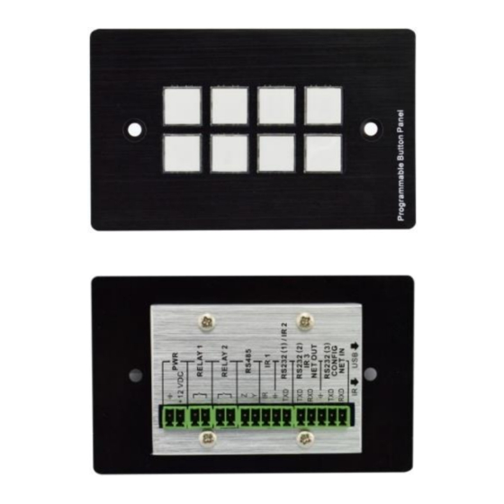
Programmable Control Panel for it) 2.2 Side Panel Mini USB Connector: 1. Communicate with PC which uses PS-WP to program the buttons. 2. Transmit the infrared data when learning IR (Optional). Infrared sensor port: receive and learn the IR code, to build the IR database. -
Page 8: Rear Panel
④ ② VL120018 has various ports in the rear panel, including Lopping port, RS232 port, RS485 port, IR port, Relay port and Power port. Below is the introduction: ① Power connector: 12VDC. Be sure that the “+” and “-” never be mixed or wrong connection. -
Page 9: Connections
3. Connections 3.1 System Diagram VL120018 can active different ports at one time. It means every button can send the RS232 and RS485 commands, IR code and control the relay at the same time. The demo system diagram as below: 3.2 Connection of Programming and Looping... - Page 10 ID of each programmable control panel by PS-WP. The ID number is from 01 to 99, and it also is the class of VL120018 in the loop, different programmable control panels should set to different ID. After connections finish, we can set the control modes by PS-...
-
Page 11: System Operations
There are USB driver file and PS-WP software in the disk. The PS-WP can run directly without installation. But when connect VL120018 with PC by USB, it may need to install the USB driver. Use the driver file to install the driver of USB, we can use USB to program the programmable control panel. -
Page 12: Main Menu
Programmable Control Panel We will introduce all the configurations one by one. 4.2.1 Main Menu The main menu includes file management, system model, connection type and help. 1) File management: Open/Save/Save as a configuration. After program, user can save the configuration to a file, so that you can use the same configuration next time. - Page 13 RS and IR types, depend on the uses of the two shared ports. The dialog is as the picture below: The output port set in PS-WP and the port used in VL120018 is corresponding. And there are four output types. They are showed as below form (“√” means port is...
-
Page 14: Panel/Key Setting
Programmable Control Panel 3) Connection type: the instructions are in the picture below: 1:Com, connect by serial port. 2:USB, connect by mini USB. 3:Disconnect, disconnect the connection. 4:Upload: upload the programmed data to the programmable control panel. It will clear all the old data in the programmable control panel. - Page 15 Programmable Control Panel Key Action Type: 1. Press: Execute events when press button. 2. Release: Execute events when release button. 3. Page: Built-in most 4 actions, actions need to be switched by other buttons, press to execute. 4. Toggle: Built-in most 4 actions, actions will loop run when press.
-
Page 16: Action List
3. Yellow Keys: Keys 33-36, all are virtual keys. Key 33 and 34 are for I/O control, which is not supported with VL120018. Key 36 is a start action, if add events to this action, when VL120018 is power on, it will execute the events in this action. Key 35 is delay button, there are three time slots can be set. -
Page 17: Event Setting
Programmable Control Panel Event setting Event setting includes RS232, IR, I/O, Relay, Delay, Compare, LED, Page, Loop and Toggle setting. Before set events, an action must be added first. The following introduction will show you the setting of each event: ... - Page 18 Programmable Control Panel 2) There are two send types: send once and send more times. When select “more times”, the send times and the delay between times can be set. See in picture below: 3) The send port must be selected as the same as model setting, otherwise the event cannot be added.
- Page 19 Programmable Control Panel Notice: When editing finish, remember to save the editing, and then press “OK”. There are two send types: send once and send more times. When select “more times”, the send times and the delay between times can be set. See in picture below: The send port must be selected as the same as model setting, otherwise the event cannot be added.
- Page 20 RS232 command to the controlled device, the device will send back a feedback. If we add the correct feedback in the data, VL120018 will compare it with the feedback received from controlled device, to verify the command is work or not. The compare...
- Page 21 If the compare is incorrect, the event behind compare will not be executed. LED setting This item is used for set the button LEDs in VL120018 to turn on/off. The setting is as below:...
- Page 22 Programmable Control Panel Page setting White buttons can be set to type “page” that include four actions. To change different actions, it will need other white buttons to active the page action number. Here take a example to show you the use of this function: Take button1 for example: click key1 and select the action type “page”, add the four actions to the action list.
- Page 23 Programmable Control Panel Then set the “page” event to make four “press” actions to active the four page number: key5-num1, key6-num2, key7-num3 and key8-num4. It will perform like this: a) When press the button5 and then button1, the button1 will execute the event of num1, press button1 more times it will execute num1 more times;...
-
Page 24: Event List
Programmable Control Panel The setting steps of toggle are similar with the page setting. But toggle performs differently, for the actions in it are loop running, it will perform as below (take the same example like page function): a) When press the button5 and then button1, the button1 will execute the event of num1, press button1 more times it will execute num2, then num3->num4->num1 and so on. - Page 25 Programmable Control Panel...
-
Page 26: Specification
Programmable Control Panel 5. Specification Specification 3 x RS232, 1 x RS485, 3 Program Port USB or RS232 Output Port x Infrared, 2 x Relay Serial Control Baud Rate 9600 baud, 8 data bits, 1 RS232 Port And Protocol stop bit, no parity Software PS-WP Temperature... -
Page 27: Troubleshooting & Maintenance
Programmable Control Panel 7. Troubleshooting & Maintenance 1) When the control panel cannot work, please check and make sure the power cord connection is well, plug cannot be mixed or connect wrong. Then restart, if still not work, the control panel may be broken. Please send it to the dealer for repairing. 2) When USB cannot open or without response, please make sure the USB driver is installed correctly, and then reconnect the USB cable. -
Page 28: After-Sales Service
Programmable Control Panel 8. After-sales Service If there appear some problems when running the device, please check and deal with the problems reference to this user manual. 1) Product Limited Warranty: We warrant that our products will be free from defects in materials and workmanship for three years, which starts from the first day the product leaves warehouse (traceable through the SN mark).
Need help?
Do you have a question about the VL120018 and is the answer not in the manual?
Questions and answers