
Subscribe to Our Youtube Channel
Related Manuals for Lumascape ZDClink

Summary of Contents for Lumascape ZDClink
- Page 1 ZDClink ® Controller with Luxor® Technology OWNER’S MANUAL LUXOR LED Landscape Lighting Controller Owner’s Manual and Installation Instructions for the ZDClink Controller...
-
Page 2: Table Of Contents
Using Other Devices with the ZDClink Controller Notes Diagnostics Screen Disable Luminaire Group Stickers Setup Screen *Use the stickers attached to the back of this guide to simplify group assignments when programming luminaires at the ZDClink Controller facepack or with the Light Assignment Module. -
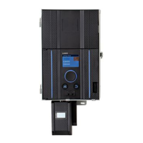
Page 3: Zdclink Controller Overview
ZDClink Controller Overview The ZDClink Controller is a lighting transformer capable of Note controlling groups of lights that are initiated by programmed The ZDClink Controller is intended for use with events. These events are adjustments of light intensity at set Lumascape low-voltage LED luminaires or devices times. -
Page 4: Glossary Of Terms
Color: The visual combination of hue and saturation lighting system where the suitability of the combination shall be Primary Controller: ZDClink Controller containing a facepack determined by local inspection authorities having jurisdiction. Do not connect two or more power supplies in parallel. Not for Satellite Controller: Controller without a facepack use in dwelling units. -
Page 5: Installing The Zdclink Controller
6) without using wall anchors. If a 120 V power source is not available at the desired All ZDClink Controllers come equipped with a 5' (1.5 m), 12 AWG transformer installation location, hire a licensed electrician (2.05 mm), three-prong electrical power cord. Only use the to run a dedicated 120 V, 15 A circuit to the desired location. - Page 6 Installing the ZDClink Controller Figure 3: Wall mounting Mounting brackets 120 V power outlet Power cord 12" (30.5 cm) minimum 1½" (3.8 cm) conduit Side View Front View...
- Page 7 Installing the ZDClink Controller Figure 4: Post mounting Mounting brackets 1½" (3.8 cm) conduit 12" (30.5 cm) minimum 4" x 4" (10.2 cm x 10.2 cm) post Concrete footing Side View Front View...
-
Page 8: Running Cable To The Luminaires
(30 m) away. 2. Use the proper cabling method for the application. Center- the luminaires. Lumascape low-voltage LED luminaires require load all cable runs to minimize the voltage differential between 10 and 15 V for optimal operation and longevity. This is between luminaires. - Page 9 Installing the ZDClink Controller Summary For maximum light output and LED life, each luminaire should be provided with 10 to 15 VAC (ZD) and 11 to 15 VAC (ZDC). Cable Stats Low-voltage lighting systems are typically installed using stranded, direct-burial-rated cable. The most common cable used is 12/2 AWG (2.05 mm) stranded cable.
-
Page 10: Low-Voltage Cable
10 to 15 V (or 11 to 15 V for luminaires with ZDC Technology). Connecting Cables at the Terminal Block Transformer terminal block: The ZDClink Controller includes two Common lugs and two 15 V lugs. Common Lugs: One conductor from each cable run coming from the lights to the transformer must be connected to one of the common lugs. -
Page 11: Operating The Zdclink Controller
All category options are located on the right side of the Home screen and are selected using the main scroll wheel. Turn the The ZDClink Controller contains only three user interface scroll wheel clockwise or counterclockwise until the desired elements: category is highlighted in light blue. -
Page 12: Activity Screen
Operating the ZDClink Controller Activity Screen Diagnostics Screen After five minutes of inactivity, an Activity screen will appear on Assigned: Controller assigned the LCD screen if the lights are running. The wait time is reduced Communicating: Controller communicating to only five seconds when the current screen is the Home screen. -
Page 13: Setup Screen
Operating the ZDClink Controller Setup Screen All background tools and settings (except color) are accessible in the Setup screen. Scroll through the various options to set up the controller. Time/Date • Set the three time categories (Hr:Min:Sec) to the current... -
Page 14: Language
Operating the ZDClink Controller Language • The coordinate settings are automatically saved after each press of the scroll wheel. Select the Home button to leave the In the Setup screen, select the language field by pressing the Location screen. scroll wheel and turning it to the desired language. Press the •... -
Page 15: Assign
Operating the ZDClink Controller Assign Restrict When compatible luminaires are plugged into the luminaire The restrict function prevents changes to themes. programming ports, the assign screen will automatically display. From the Home screen, navigate to the Setup and select The Assign screen is also accessible under the Setup menu. -
Page 16: Backup
The backup function saves all information entered into the controller, including programs, themes, colors, and setup data. To create a backup file for your ZDClink Controller, follow the steps below. Insert an SD card into the side of the facepack with the pins facing toward the front of the facepack. -
Page 17: Assigning Luminaires Into Groups
3. The assigned group number is stored in the device (e.g., LED board, lamp, CUBE) and not in the facepack. Thus, power loss or other errors within the ZDClink Controller will not affect the luminaire assignment. If a device is replaced, the new device must be programmed to the desired group number. -
Page 18: Setting Up Programs
Operating the ZDClink Controller Setting Up Programs The % field specifies the desired intensity for each event. Values range from 0% (off) to 100%. Theme events are limited to The Programs screen is where all daily running programs are On or Off. -
Page 19: Calendar-Based Programming
Operating the ZDClink Controller Calendar-Based Programming Themes Calendar-based programming allows program(s) to run during A theme is a planned set of groups at stated colors and specific dates throughout the year. intensities. A user can call up themes in the Program menu for... -
Page 20: Manual Mode
Operating the ZDClink Controller Select the Test Theme checkbox to temporarily turn on all 5. Set the duration, or the amount of time that the group groups that have been set in a theme. While this function is will run. -
Page 21: Color
Color Selection screen. Adjust the Hue (top) and/or Saturation Colors are selected on the Color Palette screen. The ZDClink (bottom) by selecting the appropriate chart, scrolling left Controller can store up to 250 preset colors, labeled numerically or right until the desired setting is located, and pressing as seen in Figure 20. -
Page 22: Color Wheel
Operating the ZDClink Controller • The test group column allows the user to view the created Color Wheel color of a specific group. The color will remain active until the The color wheel feature scans through all 300 hues constantly color palette screen is exited or the test group is set to off. -
Page 23: Technology
Operating the ZDClink Controller Mixing Standard, ZD Technology®, and ZDC Technology® Lumascape offers a variety of LED boards with ascending functionality when used with the ZDClink Controller. The standard board is zoneable, the ZD Technology board offers zoning and dimming, and ZDC Technology encompasses the first two and adds color to the mix. -
Page 24: Using Other Devices With The
Lumascape low-voltage LED boards. Two of those devices that converts incandescent luminaires to energy-efficient include the ZDClink CUBE and the ZDClink MR-16 ZD LED Lamp. LED luminaires. When connected to a ZDClink Controller, the MR-16 ZD adds zoning, dimming, and control capabilities to any ZDClink CUBE brand of low-voltage luminaire that has an MR-16 socket. -
Page 25: Disable
Operating the ZDClink Controller Disable The Disable option allows you to completely shut down all lighting events in the Manual and Program modes regardless of time or status, indefinitely. This mode does not turn off the unit but rather suspends all lighting events until the user decides to reactivate. -
Page 26: Controller Linking Setup
Controller Linking Setup ZDClink Linking allows for a single point of control for sites Linking firmware is required for the chassis. that require multiple ZDClink Controllers. A linking system can Updating to Linking contain a total of nine satellite controllers. -
Page 27: Wired Connection For Satellite Controllers
ZDClink Linking Setup Wired Connection for Satellite Controllers 4. If site requires multiple satellite controllers, insert new Cat 6 cable into the unused linking port of the previous Disconnect power to the primary and satellite controllers. satellite controller. 2. Insert one end of Cat 6 cable into the linking port of the 5. -
Page 28: Chassis Communication And Assignment
(LINK-MOD in North America or LINK-MOD-E outside North controller has been "Assigned" and is "Communicating." America) will be installed on the primary ZDClink Controller. For more information on Wireless ZDClink Linking setup, use the link below. Figure 31: Diagnostics screenshot 3. -
Page 29: Care And Maintenance
Check aiming angles. Semiannually Check, adjust, and replace all cable and cable ties in trees. As needed Note When replacing luminaire LED boards, be sure to use Lumascape LED boards. Use of other brands may cause the luminaire to malfunction. -
Page 30: Troubleshooting
Note Shorts and overloads are not covered by the Lumascape warranty and can be detected only when the transformer is tested in the field. Periodic system maintenance is required to keep your Lumascape lighting system operating at peak performance. -
Page 31: Firmware Updates
Controller, an SD card is required to transfer the data from a computer to the facepack. Go to the Lumascape website (lumascape.com) and navigate to the ZDClink product page. The firmware update files are located under the Downloads tab. 2. Save the desired firmware onto an SD card. - Page 32 Care and Maintenance Figure 34: Setup screen (firmware) Figure 35: Firmware load screenshot 7. Select the Firmware Type that will be updated. 8. Once the designed type is selected, navigate to Update and press the scroll wheel. The facepack and flash update processes usually take between 5 and 15 seconds, chassis updates typically take a couple of minutes, and luminaire updates can take up to 15 minutes.
-
Page 33: Fuse Replacement
If the unit is powering on, but the luminaires attached are not receiving power, the fuse may need to be replaced. To replace the fuse, follow the directions below: Unplug the ZDClink Controller from power. 2. Remove all wires from the Common and 15 V terminals on the chassis. -
Page 34: System Reset
Care and Maintenance System Reset There are two types of system resets: facepack reset and database reset. The facepack reset simply removes power to the facepack and restarts the firmware. A database reset deletes the entire database to allow the user to start from scratch. All program data is lost during a database reset, but luminaire assignments remain intact. -
Page 35: Database Reset
Care and Maintenance Database Reset Chassis Indicator Lights From the Home screen, push the Home button and the Back An indicator light displays the communication status of the button simultaneously to bring up the Diagnostics screen chassis to the facepack. The following colors indicate the (Figure 2 on page 3). -
Page 36: Warranty
This warranty extends only to the original installer of the product. If a defect arises in a Lumascape product or part during the warranty period, contact the local authorized manufacturer’s representative. - Page 37 Warranty Regulatory and Legal Information This equipment has been tested and found to comply with To satisfy FCC RF Exposure requirements for mobile and base the limits for a Class B digital device, pursuant to part 15 station transmission devices, a separation distance of 20 cm or of the FCC Rules.
-
Page 38: Notes
Notes... - Page 39 Notes...
- Page 40 Lumascape | Architectural & Facade Lighting 1940 Diamond Street, San Marcos, CA 92078 USA lumascape.com LU-005-OM-EN A 5/22 © 2022 Hunter Industries™. Hunter, Lumascape, all related logos, and all other trademarks are property of Hunter Industries, registered in the U.S. and other countries.
-
Page 41: Luminaire Group Stickers
Luminaire Group Stickers To simplify installation, use these stickers when programming luminaires at the ZDClink Controller facepack or with the Light Assignment Module. Place the stickers on luminaire wires to create a visual reference for group numbering in the field. - Page 42 Luminaire Group Stickers To simplify installation, use these stickers when programming luminaires at the ZDClink Controller facepack or with the Light Assignment Module. Place the stickers on luminaire wires to create a visual reference for group numbering in the field.
Need help?
Do you have a question about the ZDClink and is the answer not in the manual?
Questions and answers