Table of Contents
Advertisement
Quick Links
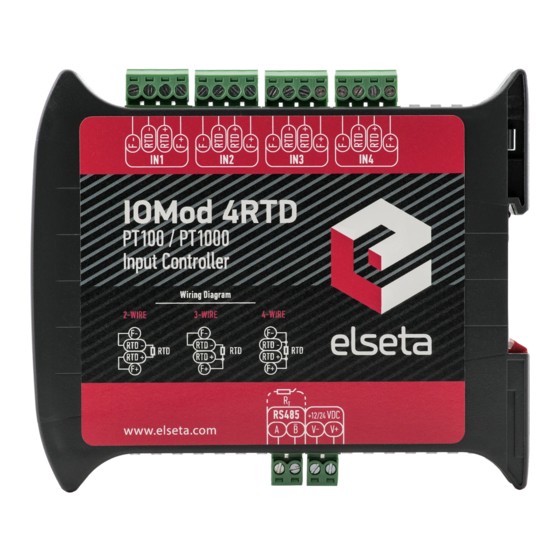
IOMOD 4RTD User Manual Modbus
Introduction
IOMOD 4RTD is used for temperature data monitoring over Modbus or IEC-60870-103 using resistance temperature
detector (RTD) platinum sensors. Up to 4 RTD temperature sensors can be connected at once.
Features
● Temperature sense with ±0.5 °C accuracy over all operating conditions;
● Selectable PT100 ar PT1000 RTD temperature sensor for every channel (2, 3 or 4 wire);
● 2.5kV(rms) isolated RTD inputs;
● Configurable temperature and sensors' fault detection for every channel;
● Temperature sensing range from -200 up to 800 °C when using platinum RTD sensors;
● Configurable Modbus or IEC-60870-103 settings: Slave ID, baud rate, parity and stop bits, RS485 terminating
resistor, etc.
● Firmware upgrade over USB.
Operational Information
IOMOD uses Modbus (RTU) or IEC-60870-103 protocols over RS485 connection, which can be used for cable lengths up
to 1500 meters and connect up to 30 devices on one line. Default Modbus and IEC-60870-103 settings are: 9600
bauds/s baudrate, 8N1, Slave (Link) address - 1.
To read temperature using Modbus (RTU) protocol user can use device with default settings without configuring it. To
read temperature from RTD sensor, send 04 Modbus command (Read Input Registers) with resolution of two registers
from 0 to 7. Odd numbers represent least significant words, even numbers represent most significant words. For
example, to read temperature measured by first RTD, read register 0 and 1, where register 0 is least significant word.
Two words read by Modbus represent a float type (IEEE-754 compatible) variable.
For further information regarding setting temperature parameters and configurable options please refer to table shown
below, also supported MODBUS functions described in paragraphs described below.
CONFIGURABLE OPTIONS
Slave Address
Baudrate
Data, Stop and Parity bits
RS485 Terminating Resistor
RTD parameters
Default settings
Setting temperature limits
Fault configuration
Status LED
Status LED can be in 2 colors :
Blue - Device connected to USB.
Green - Normal operation.
Rx/Tx LED
The RX/TX LED on the IOMod flashes when data is either being transmitted or received via the RS485 port.
OVER USB
Yes
Yes
Yes
Yes
Yes
Yes
Yes
Yes
OVER MODBUS
No
No
No
No
No
No
Yes
Yes
Advertisement
Table of Contents

Summary of Contents for Elseta IOMOD 4RTD
- Page 1 IOMOD 4RTD User Manual Modbus Introduction IOMOD 4RTD is used for temperature data monitoring over Modbus or IEC-60870-103 using resistance temperature detector (RTD) platinum sensors. Up to 4 RTD temperature sensors can be connected at once. Features ● Temperature sense with ±0.5 °C accuracy over all operating conditions;...
-
Page 2: Supported Modbus Functions
Supported MODBUS functions 01 (0x01) Read Coil Status Used to read fault flags. Fault is implemented as high logic level if any configured fault has occurred, zero otherwise. Fault flags are cleared automatically if possible. 03 (0x03) Read Holding Registers May be used to read holding registers containing temperature limits defined by user in degrees Celsius, fault mask register. -
Page 3: Technical Information
Fault register (R-0) (R-0) (R-0) (R-0) (R-0) (R-0) (R-0) (R-0) Temperature Temperature Hi Threshold Lo Threshold (R-0) (R-0) (R-0) (R-0) (R-0) (R-0) (R-0) (R-0) RTD Code Hi RTD Code Lo RTD REFIN- > RTD FORCE Overvoltage/ Threshold Threshold 0.85 x VBIAS Open Undervoltage Fault mask register... -
Page 4: Device Connection
Fig. 5.1. Typical IOMod connection diagram IOMOD 4RTD has 1/8 Unit load receiver which allows to have up to 256 units on line (compared to standard 32 units). To reduce reflections, keep the stubs (cable distance from main RS485 bus line) as short as possible when connecting device. -
Page 5: Usb Interface
Fig. 5.3. RTD sensor colour codes IOmod 4RTD accepts 2-wire, 3-wire or 4-wire connection types of RTD sensors (PT100, PT1000). Firstly, select a sensor type (PT100 or PT1000) using a USB terminal. Secondly, use the following instructions depending on the number of wires of a selected RTD sensor. - Page 6 (folder in which x64 and x86 lay inside, as in Fig. 6.3). Fig. 6.3. Device driver folder content IOMod 4RTD configuration via PuTTY terminal Configuration of IOMOD device is done through CLI (Command Line Interface) on virtual COM port. Drivers needed for MS Windows to install VCOM will be provided.
- Page 7 Fig. 6.4. The main menu for IOMod 4RTD Navigation is performed by pressing number connected to its function. User then should proceed by following further on-screen instructions. For example, to set desired slave address, press [1] to enter Slave Address screen; enter new configuration;...
- Page 8 Testing With “THE VINCI” software To test IOMOD 4RTD with default settings, user can connect device through RS485 to Modbus or IEC-60870 (depending on firmware) master or using USB Simulation Mode. Example will show The Vinci Expert as serial interface converter and adapter to PC with The Vinci software.
- Page 9 Fig.6.8. Representing temperature as float when using Modbus Fig. 6.8. represents how The Vinci software should be configured to represent temperature in IEEE- 754 standard float type when using Modbus communication. Revision #4 Created 1 December 2021 13:47:53 by Tautvilis Updated 3 May 2022 08:26:01 by Simas...
Need help?
Do you have a question about the IOMOD 4RTD and is the answer not in the manual?
Questions and answers