Advertisement
Quick Links
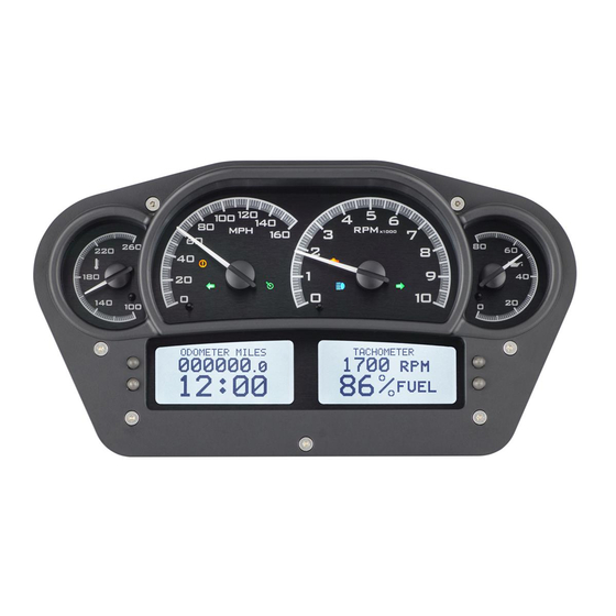
The VHX-1100 and VHX-1200 systems have additional display area to provide more functionality. These systems can
display data from any BIM module attached to the system as well as several gauge values from the control box
sensors.
These versions contain four switches in the face which are used as SW1 and SW2 with the use of the switch harness
provided, and SW3 and SW4, which are internal to the VHX system.
SWITCH HARNESS CONNECTION:
TO REAR OF DISPLAY
Connect the orange wire to SW1 (-) terminal on VHX control box. Upper left switch will be SW1 (speed display).
Connect the green wire to SW2 (-) terminal on VHX control box. Lower left switch will be SW2 (tach display).
Leave the blue wire disconnected (not used). SW3 and SW4 are internal with no additional connections needed.
Upper right switch will be SW3. Lower right switch will be SW4.
Operating Manual and Switch Connections for
VHX-1100 & VHX-1200 Systems
VHX
control
DISPLAY
CABLE
box
VHX
CONTROL BOX
www.dakotadigital.com
techsupport@dakotadigital.com
605-332-6513
ORANGE
ORANGE (switch 1)
GREEN (switch 2)
BLUE (switch 3)
VHX-1100 shown below
1
AUX.
I/O
GREEN
MAN #650431:A
Advertisement

Related Manuals for Dakota Digital VHX-1100-K-W


Summary of Contents for Dakota Digital VHX-1100-K-W
- Page 1 Operating Manual and Switch Connections for VHX-1100 & VHX-1200 Systems The VHX-1100 and VHX-1200 systems have additional display area to provide more functionality. These systems can display data from any BIM module attached to the system as well as several gauge values from the control box sensors.
- Page 2 AVAILABLE SCREENS: The following screens are ONLY available on LCD1 or LCD2 (see main VHX manual for settings): Message displays Default LCD DESCRIPTION ODOMETER Odometer reading (0-999,999) A MILES Trip A odometer reading (0-9999.9) B MILES Trip B odometer reading (0-9999.9) SERVIC (when enabled) Distance to next service (0-9,999, or ---- when past due) ENGINE...
- Page 3 SETUP This VHX system has two different setup menus that can be used to configure your VHX system. The first is the controller setup. The second is the display head setup. The controller setup allows you to configure how the control box connects to your vehicle, what senders are used and also allows you to do some setup on many connected expansion modules.
- Page 4 TEMPERATURE UNIT ( TEMP UNIT This option sets the unit used to display temperature readings when displayed in LCD3 or LCD4. The two options are F (Fahrenheit) and C (Celsius). Default setting is F. Enter setup by pressing SW3 and turning key on Press and Release SW3 until “TEMP UNIT”...