Table of Contents
Advertisement
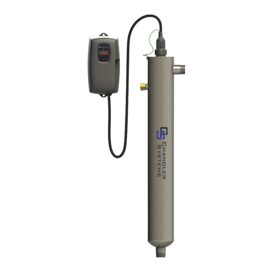
Operation & Installation Instructions
UV
Series
UV-H
Series
CHANDLER - Standard Systems
System
Rated Flow
UV-2
UV2D
2 gpm
UV2DM
UV-3
UV3D
3 gpm
UV3DM
UV-6
UV6D
6 gpm
UV6DM
UV-11
UV11D
11 gpm
UV11DM
UV-15
UV15D
15 gpm
UV15DM
UV-20
UV20D
21 gpm
UV20DM
UVD / M
Series
System
UV-5H
UV-5DH
UV-5DHM
UV-10H
UV-10DH
UV-10DHM
UV-15H
UV-15DH
UV-15DHM
UV-25H
UV-25DH
UV-25DHM
UV-40H
UV-40DH
UV-40DHM
UV-DH / M
Series
Rated Flow
5 gpm
10 gpm
15 gpm
25 gpm
40 gpm
Advertisement
Table of Contents

Related Manuals for Chandler Systems UV-2

Summary of Contents for Chandler Systems UV-2
- Page 1 Operation & Installation Instructions UV-H UVD / M UV-DH / M Series Series Series Series CHANDLER - Standard Systems System Rated Flow System Rated Flow UV-2 UV-5H UV2D 2 gpm UV-5DH 5 gpm UV2DM UV-5DHM UV-3 UV-10H UV3D 3 gpm UV-10DH...
- Page 2 Congratulations on purchasing this ultraviolet disinfection system. By purchasing a CHANDLER UV Disinfection system you are receiving not only a high quality product but also peace of mind. Protecting your water supply with a UV system gives you reassurance that your family will have access to safe drinking water throughout your entire home with no chance of microbiological contamination.
-
Page 3: Table Of Contents
System Troubleshooting..................18 Temperature Management Devices ................. 20 Expansion Modules ......................20 CHANDLER Standard Output System Specifications ............22 CHANDLER (High Output System Specifications) .............. 23 Chandler Systems Limited Warranty Statement ............... 24 Warranty Registration ...................... 25 P a g e... -
Page 4: Safety Considerations
Safety Considerations Although your UV system has been manufactured to the highest safety standards, care must be followed when operating and/or maintaining your system. 1. Before servicing this equipment, disconnect the power cord from the electrical outlet. 2. Energy given off by the UV lamp is harmful to your eyes and skin. NEVER look directly at an illuminated UV lamp without adequate eye protection and always protect your skin from direct exposure to the UV light. -
Page 5: Water Quality Parameters
Water Quality Parameters UV disinfection is extremely effective against microorganisms but only if the UV light can pass through the water it needs to treat. This means that the quality of your water is very important in order to ensure complete disinfection. Treated water should be tested for at the least the parameters listed below. -
Page 6: Assembly
Assembly Unpack the system and ensure all the components are included with the system. Your system is shipped with the following components: CHANDLER (Standard output lamp systems) LAMP KEY GLAND NUT CONTROLLER 320006 “UV” SYSTEMS O-RING UVC-4 North American UV D/UV DM SYSTEMS 310038 UVC-5 North American UV LAMP... - Page 7 CHANDLER-HO (High output lamp systems) LAMP KEY GLAND NUT CONTROLLER 320006 UV H SYSTEMS O-RING UVC-4H 310038 (fits all units) UV DH/UV DHM SYS- UV LAMP TEMS UVLMP-4H “-5” series UVC-4H UVLMP-10H “-10” series (fits all units) UVLMP-15H “-15” series UVLMP-25H “-25”...
-
Page 8: System Sizing
System Sizing All CHANDLER UV systems are rated for a specific flow rate in water that meets the quality pa- rameters on page 5. PLEASE NOTE that increasing the flow above this rating or disinfecting water that does not meet the quality parameters will decrease the dose and therefore compromise the microorganism inactivation. -
Page 9: Installation
To facilitate lamp removal, ensure there is enough space at the lamp connector end to safely remove the UV lamp and/or quartz sleeve (See Figure 2). The controller will require a ground fault circuit interrupter (GFCI or GFI) outlet and should be mounted beside or above the reactor. PLEASE NOTE: All CHANDLER UV disinfection systems are intended for indoor use only as they should not be exposed to the elements. - Page 10 Step 6: Once the system has been plumbed in, gently remove the quartz sleeve from its packaging being careful not to touch the length with your hands. The use of cotton gloves is recommended for this procedure as oils from the hands can leave residue on the sleeve and lamp which can ultimately block the UV light from getting to the wa- ter.
- Page 11 Step 11: Always hold UV lamps by their ceramic ends, not by the lamp quartz. Remove the lamp from its packaging. Again, the use of cotton gloves is recommended. Remove the lamp key from the lamp’s connector and set it aside for the next step. Be careful to not touch the key’s exposed contacts.
-
Page 12: System Disinfection
System Disinfection With a new installation, or any time the UV system is shut down for service, without power, or is inoperative for any other reason, the lines in the home or facility could be contaminated. Use the following steps to fully disinfect the lines throughout the entire home or facility. Step 1: Check for and remove any “dead ends”... -
Page 13: Cleaning The Uv Sensor
CHANDLER systems come with a feature laden controller that incorporates both the lamp driver (ballast) and control features in one water-tight case. Four main controllers are available for the CHANDLER systems (depending on your model). All four models feature a power factor cor- rected, constant current lamp driver with a universal power input. -
Page 14: Uv" Controllers
“UV” Controllers Simplistic in operation, these systems feature a tri-colour LED that indicating system status and a 4-digit display to in- dicate lamp life remaining. Pressing the button will change the display to indicate total running time. When the UV lamp is on and within its operating age, the LED will be green. -
Page 15: Uv D & Uv Dh Operational Screens
A final module screen is displayed showing which specific modules were initialized. The controller then displays the lamp optimization screen for 60 seconds to allow the lamp to reach its optimum output. Finally, a final “start-up complete” screen is displayed. The system will now be ready to disinfect water flow. -
Page 16: Lamp Countdown Sequence
audible chirp every audible chirp every constant audible cycles with red low 15 seconds 15 seconds alarm uv screen Lamp Countdown Sequence The system counts down the number of days until a lamp change is required. UV D/DM & UV DH/DHM UV / UVH At thirty days remaining, the LED or display screen will change to a yellow caution indicator. -
Page 17: Lamp Replacement (Uv / Uvh Systems)
System Service Suggested UV D & UV DH controllers will display the System Service Suggested Screen every 6 months to remind consumers to maintain both their UV and other prefiltration. This will serve as a prompt only and will not put the system into alarm. -
Page 18: System Troubleshooting
System Troubleshooting Hard Alarms: The following give a constant audible alarm. If present, the solenoid valve is closed, and the 4-20, remote alarm and WiFi modules transmit the alarm. System Display Problem Resolution Reset lamp protection circuit -unplug unit for 10 seconds. The system has detected Replace the lamp with the a problem with the... - Page 19 Soft Alarms: The following remaining errors give a 15 second audible chirp only System Display Problem Resolution Ensure all modules are connected properly to the system and to each other. Modules can be tested indi- The module indicated is vidually by plugging in one no longer communicat- at a time and cycling power ing to with the system.
-
Page 20: Temperature Management Devices
Temperature Management Devices Your CHANDLER UV system is designed to run continuously to ensure optimal disinfection. However, during periods when no water is drawn through the system, the energy from the disinfection process can cause the temperature of the water inside the chamber to rise. In extreme situations elevated water temperature or the fluctuation in temperature can lower the output of the UV lamp. - Page 21 SOLENOID CONNECTION MODULE: Connects a NORMALLY CLOSED line voltage solenoid valve to the system. On a non-monitored system, the sole- noid will only close on a lamp failure error. On a monitored system, the solenoid is closed when the UV level drops below 50%. Also note that in cases where emergency use of untreated water is re- quired, the controller can be placed into a manual override mode allowing for the flow of water in an...
-
Page 22: Chandler Standard Output System Specifications
CHANDLER Standard Output System Specifications CHANDLER EQUIPMENT SPECIFICATIONS Residential systems (standard output lamps) Multi-Use / UV11 UV15 UV20 MODEL UV2D UV3D UV6D UV11D UV15D UV20D UV2DM UV3DM UV6DM UV11DM UV15DM UV20DM 3.8 gpm 6.1 gpm 11 gpm 20 gpm 30 gpm 39 gpm Flow Rate 15 lpm... -
Page 23: Chandler (High Output System Specifications)
CHANDLER (High Output System Specifications) CHANDLER EQUIPMENT SPECIFICATIONS Residential Crossover systems (high output lamps) UV-5H UV-10H UV-15H UV-25H UV-40H MODEL UV-5DH UV-10DH UV-15DH UV-25DH UV-40DH UV-5DHM UV-10DHM UV-15DHM UV-25DHM UV-40DHM 5.0 gpm 10 gpm 15 gpm 25 gpm 40 gpm Flow Rate 18.91 lpm 37.9 lpm... -
Page 24: Chandler Systems Limited Warranty Statement
Chandler Systems Limited Warranty Statement Products manufactured by CHANDLER are warranted to the original user only to be free of de- fects in material and workmanship for a period as specified below. This warranty only applies to the original purchaser and is not transferable. -
Page 25: Warranty Registration
TO GET WARRANTY SERVICE To obtain service under this warranty, you must first contact CHANDLER Customer Service at (888) 363-9434 to obtain a Warranty Return Authorization. You will then need to return the product through the CHANDLER Dealer or Distributor where the product was originally pur- chased, together with proof of purchase and installation date, failure date, and supporting in- stallation data. - Page 26 2 6 | P a g e...
- Page 27 2 7 | P a g e...
- Page 28 Chandler Systems 710 Orange Street Ashland, OH 44805 Phone (888) 363-9434 www.chandlersystemsinc.com PN#910181 Version Date: 03-2020...
Need help?
Do you have a question about the UV-2 and is the answer not in the manual?
Questions and answers
Is The UV 11D system NSF certified?