Table of Contents
Advertisement
Quick Links
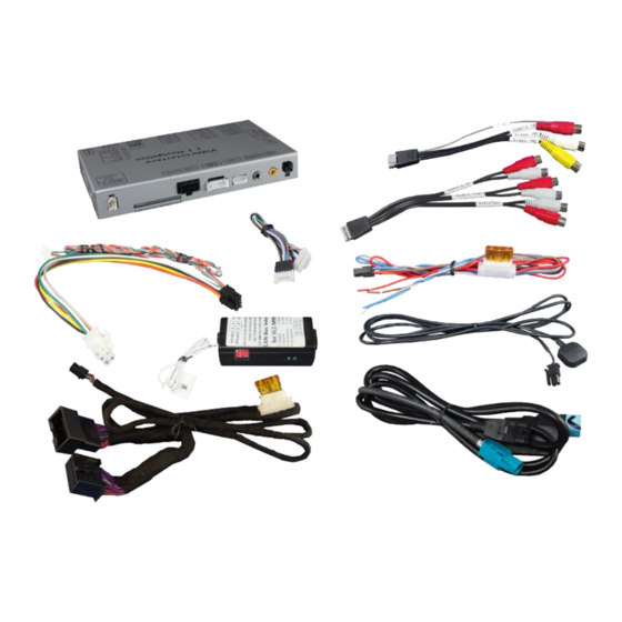
Audi MMI3G basic/high, MMI3G+ basic/high and
VW RNS850 navigation systems
with 4pin HSD LVDS connector
Video-inserter with 2 video + RGB + rear-view camera input
Product features
Video-inserter
2 CVBS video-inputs for after-market devices (e.g. DVD-Player, DVB-T tuner, ...)
Built-in audio-switch (no audio-insertion)
Rear-view camera CVBS video-input
Automatic switching to rear-view camera input on engagement of reverse gear
RGB-input for after-market navigation
Video-in-motion (ONLY for connected video-sources)
Compatible with factory rear-view camera
AV-inputs PAL/NTSC compatible
Version 21.02.2017
v.LiNK Video-inserter
CI-VL2-MMI3G-Q3
CI-VL2-MMI3G-GW
Compatible with
Advertisement
Table of Contents

Subscribe to Our Youtube Channel
Summary of Contents for v.link CI-VL2-MMI3G-Q3
- Page 1 Video-inserter CI-VL2-MMI3G-Q3 CI-VL2-MMI3G-GW Compatible with Audi MMI3G basic/high, MMI3G+ basic/high and VW RNS850 navigation systems with 4pin HSD LVDS connector Video-inserter with 2 video + RGB + rear-view camera input Product features Video-inserter 2 CVBS video-inputs for after-market devices (e.g. DVD-Player, DVB-T tuner, …) ...
-
Page 2: Table Of Contents
Contents 1. Prior to installation 1.1. Delivery contents 1.2. Checking the compatibility of vehicle and accessories 1.3. Boxes and connectors 1.3.1. CAN-box 1.3.2. Video-Interface 1.3.2.1. Dip-switch settings 1.3.2.2. Enabling the interface’s video inputs (dip 1-3) 1.3.2.3. RGB-video input signal selection for after-market navigation (Dip 4) 1.3.2.4. -
Page 3: Prior To Installation
Legal Information By law, watching moving pictures while driving is prohibited, the driver must not be distracted. We do not accept any liability for material damage or personal injury resulting, directly or indirectly, from installation or operation of this product. This product should only be used while standing or to display fixed menus or rear-view-camera video when the vehicle is moving, for example the MP3 menu for DVD upgrades. -
Page 4: Checking The Compatibility Of Vehicle And Accessories
Navigation system (with Item no. 4pin HSD video connector) Audi Q3 (8U) All head-units with monitor CI-VL2-MMI3G-Q3 Audi A1 (8X), Q7 (4L) All head-units with monitor Audi A4 (8K, 8K allroad), A5 (8T), A6 (4F, 4F allroad), A6 (4G) till about... -
Page 5: Video-Interface
1.3.2. Video-interface The video-interface converts the connected after-market sources video signals to an LVDS signal which is the inserted into the factory monitor on certain trigger options. 1.3.2.1. Dip-switch settings Some settings must be selected by the dip-switches on the video-interface. -
Page 6: Rgb-Video Input Signal Selection For After-Market Navigation (Dip 4)
1.3.2.3. RGB-video input signal selection for after-market navigation (Dip 4) If an after-market RGB navigation or other RGB video source is connected, the source’s RGB output signal must match the interface’s RGB video input setting. 1.3.2.4. Rear-view camera setting (dip 5) If set to OFF, the interface switches to factory LVDS picture while the reverse gear is engaged to display factory rear-view camera or factory optical park system picture. -
Page 7: Dip-Switch Settings Of Can-Box
1.4. Dip-switch settings of CAN-box Choose the navigation the interface is to be installed in and set dip 1 to 4 according to the below table. ON ↓ Fahrzeug/Navigation Dip 1 Dip 2 Dip 3 Dip 4 A1, A4, Q3 A6, Q7 2. -
Page 8: Connection Schema
2.2. Connection schema Version 21.02.2017 CI-VL2-MMI3G-xxx... -
Page 9: Connecting Video-Interface And Can-Box
2.3. Connecting Video-interface and CAN-box Note: It is possible to use the interface without MMI-box. In this case sort the female 8pin connector out from the 6pin to 8pin cable. Connect white female 4pin Micro-Fit connector of the PNP power/CAN cable to the male 4pin Micro-Fit connector of the CAN-box. -
Page 10: Connecting Power And Can-Bus
2.4. Connecting power and CAN-bus 2.4.1. CI-VL2-MMI3G-Q3 – Connection to the climate control panel and head-unit Remove the female Quadlock connector of the vehicle harness from the rear of the Head-unit and connect it to the male Quadlock connector of the PNP power/CAN cable. -
Page 11: Vl2-Mmi3G-Gw - Connection To The Can-Gateway
2.4.2. CI-VL2-MMI3G-GW – Connection to the CAN-gateway Remove the female CAN-gateway connector of the vehicle harness from the rear of the CAN-gateway Head-unit and connect it to the male connector of the PNP power/CAN cable. Pin diagram Pin diagram CAN-gateway 4pin cable CAN-gateway •... -
Page 12: Rns850 - Cable With Open Ends
Connect female connector of PNP power/CAN cable to the male connector of CAN- gateway. Location of CAN-gateway • A1/A3 below the steering-wheel • A6/A7/A8 footwell on the passenger side below right (A6 from 2013 middle of rear bench seat) • Q5/Q3 footwell on the passenger side top left Location under the steering-wheel 2.4.3. -
Page 13: Connection To The Head-Unit
2.5. Connection to the head-unit Remove head-unit (navigation computer/radio). Connect female 8pin Micro-Fit connector of the 4pin HSD LVDS cable to male 8pin Micro-Fit connector of the video-interface. Remove female 4pin HSD LVDS connector from the rear of the head-unit and connect it to the male 4pin HSD LVDS connector of the video-interface. -
Page 14: Connecting Peripheral Devices
2.6. Connecting peripheral devices It is possible to connect an after-market RGB navigation (or other RGB video source), 2 after- market AV-sources and an after-market rear-view camera to the video-interface. Before final installation of the peripheral devices, we recommend a test-run of the interface. -
Page 15: Video-Sources To Av1 And Av2
2.6.1. Video-sources to AV1 and AV2 Connect female 6pin connector of the audio cable to male 6pin connector of the video-interface. Connect video RCA of the AV-source 1 to the female RCA connector Video 1 of the video cable. Connect video RCA of the AV-source 2 to the female RCA connector Video 2 of the video cable. -
Page 16: Audio-Switch And Audio-Insertion
2.6.2. Audio-switch and audio insertion This interface can only insert video signals into the factory infotainment and switch audio signals. If an AV-source is connected to AV1 or AV2, audio insertion must be done by factory audio AUX input, the optionally available AUX-in interface AUX-110 (only for MMI3G, not for MMI3G+)or FM-modulator to which the interface’s sound-switch output is connected. -
Page 17: After-Market Rear-View Camera
2.6.3. After-market rear-view camera Some vehicles have a different reverse gear code on the CAN-bus which the included CAN- box is not compatible with. Therefore there is two different ways of installation. If the CAN- box can detect the reverse gear in the vehicle, the green wire of the 6pin to 8pin cable should carry +12V while the reverse gear is engaged. -
Page 18: Case 2: Can-Box Does Not Detect Reverse Gear
2.6.3.2. Case 2: CAN-box does not detect reverse gear If the CAN-bus interface does not deliver +12V on the green wire of the 6pin to 8pin cable when reverse gear is engaged (not all vehicles are compatible) an external switching signal from the reverse gear light is required. -
Page 19: Video Signal Connection
2.6.3.3. Video signal connection Connect the video-RCA of the after-market rear-view camera to the female RCA port of the video-interface which is labeled as CAM. Note: Picture settings for CAM input must be done in AV2. 2.7. Connecting video-interface and keypad Connect the female 4pin connector of the keypad to the male 4pin connector of the video-interface. -
Page 20: Picture Settings And Guide Lines
2.8. Picture settings and guide lines The picture settings are adjusted by the 3 buttons on the video-interface. Press the MENU button to open the OSD settings menu or to switch to the next menu item. Press UP and DOWN change the selected value. The buttons are embedded in the housing to avoid accidental changes during or after installation. -
Page 21: Interface Operation
3. Interface operation 3.1. By factory infotainment buttons The NAV button and the MODE button of the MMI are used to execute interface functions. MMI3G Longress MODE or NAV button to switch the video-source MMI3G+ and A1 vehicles Longpress NAVI button of the steering-wheel to switch the video-source. Each press will switch to the next enabled input. - Page 22 FAQ – Trouble shooting Interface functions For any troubles which may occur, check the following table for a solution before requesting support from your vendor. Symptom Reason Possible solution Not all connectors have been reconnected to factory head- Connect missing connectors. unit or monitor after installation.
- Page 23 Symptom Reason Possible solution Camera input picture Use relay or electronics to "clean" reverse gear lamp black. Camera power taken directly power. Alternatively, if CAN-bus box is compatible Camera input picture from reverse gear lamp. with the vehicle, camera power can be taken from green wire of 6pin to 8pin cable.
Need help?
Do you have a question about the CI-VL2-MMI3G-Q3 and is the answer not in the manual?
Questions and answers