Table of Contents
Advertisement
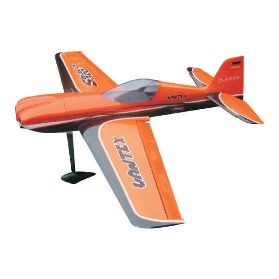
Instruction Manual
Item No: AM505
Specifications:
Wingspan: 1850mm (72.8 in)
Length: 1698mm (66.9 in)
Wing Area: 66dm2 (1023 sq in)
Flying Weight: 4.2kg (9.3 lbs)
Engine(not incl.): 26-35cc Gas or .91-1.20(2C) / 1.10-1.40(4C) Nitro
Radio(not incl.): 4ch, 6 servos
Construction: Balsa and Plywood
Features:
Designed for high performance scale aerobatics
High-quality balsa and plywood material
Light weight and strong construction
Foam brace on the back of fuselage
Hidden switch hatch design
Enhanced cowling mounting design
Hardware package included
Antenna tube included
High-quality, prepainted, fiberglass cowling and wheel pants
Nice color scheme with professional covering
Picture may not be the same as actual product. Please refer to actual product.
We reserve the rights of updating product information, appearance and parameters without notice.
Advertisement
Table of Contents

Related Manuals for Vantex Sbach 300 73" 30cc


Summary of Contents for Vantex Sbach 300 73" 30cc
- Page 1 Instruction Manual Item No: AM505 Specifications: Wingspan: 1850mm (72.8 in) Length: 1698mm (66.9 in) Wing Area: 66dm2 (1023 sq in) Flying Weight: 4.2kg (9.3 lbs) Engine(not incl.): 26-35cc Gas or .91-1.20(2C) / 1.10-1.40(4C) Nitro Radio(not incl.): 4ch, 6 servos Construction: Balsa and Plywood Features: Designed for high performance scale aerobatics High-quality balsa and plywood material...
- Page 2 Table of Contents Appendix – Parts and Options...
-
Page 3: Safety Precautions And Warnings
Introduction Step 2 Fully assemble the model. With a helper, lift the airplane with your index fingers to find the balance point. The balance point (CG) should lie between the two marks on the wing. If not, try to move some parts such as batteries to different position, or add the necessary weight to the nose or tail to obtain the correct balance. -
Page 4: Radio Setup
This warranty does not cover cosmetic damage or damage due to acts of God, accident, misuse, Radio Setup abuse, negligence, commercial use, or modification of or to any part of the Product. This warranty does not cover damage due to improper installation, operation, or maintenance. This warranty is limited to the original purchaser and is not transferable. -
Page 5: Additional Required Items
Additional Required Items Step 9 Install the switch for the ignition in the switch hatch on the side of the fuselage as shown. Radio Equipment Tools • 4-channel radio system (minimum) • Adjustable wrench (small) • 1 standard servo for throttle •... -
Page 6: Section 1 - Aileron Servo Installation
Section 1 – Aileron Servo Installation Step 2 The vertical and horizontal base lines are pre-marked on the firewall. Measure and mark the same distance from the lines for the four engine standoff screws. The firewall is already mounted correctly to provide right Required Parts offset for the engine when the engine standoff center is •... - Page 7 Step 2 Section 2 – Aileron Control Horn Wrap the receiver battery in foam and use rubber bands or hook and loop straps to secure the battery to the battery tray. Installation Required Parts Step 3 • Wing panel (left and right) Assemble the fuel tank correctly.
-
Page 8: Section 3 - Hinging And Sealing The Control Surfaces
Step 5 Step 2 From the top of the aileron, plug the control horn Install the following items onto the axle: washer, wheel screw through the hole and secure it with the provided and then wheel collar. nut. Note: It may be necessary to drill the hole in the wheel to fit onto the axle. -
Page 9: Section 4 - Aileron Linkage Installation
Step 3 Step 3 Remove the bracket and drill pilot holes at the When the epoxy is cured, work each hinge throughout its full motion several times using your hands. previously marked positions. This will break free any epoxy that may have found its way into the hinge joint. Move the hinge throughout its full travel until no resistance is felt. -
Page 10: Section 5 - Wing Installation
Step 2 Step 7 Adjust the linkage length until the hole in the ball link aligns with the outer hole in the servo arm Hinge the rudder using the same techniques as with the aileron and elevator. when the aileron is neutral and the servo arm is centered. Step 8 Step 3 Put the rudder in its neutral position and center the rudder servo. -
Page 11: Section 6 - Stabilizer Installation
Step 2 Step 3 Install the rudder servo on the right position of servo Carefully slide the remaining wing panel onto the wing tube that projects from the fuselage. The fit tray in the fuselage. Attach the servo arm to the servo. may be tight;... -
Page 12: Section 7 - Rudder Installation
Step 3 Step 8 Center the elevator servo using the radio system. Glue the elevator hinges in place using the same Install a servo arm onto the servo. techniques used to hinge the ailerons. The shortened hinges will be installed into the stabilizer towards the root.
Need help?
Do you have a question about the Sbach 300 73" 30cc and is the answer not in the manual?
Questions and answers