Table of Contents
Advertisement
Quick Links
Advertisement
Table of Contents

Related Manuals for Valterra Products Go Power! GP-SW1500TS

Summary of Contents for Valterra Products Go Power! GP-SW1500TS
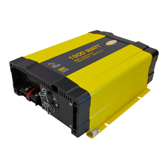
- Page 1 PURE SINE WAVE INVERTER GP-SW1500TS User Manual GP-SW1500TS © 2019 Go Power!® By Valterra Products, LLC Worldwide Technical Support and Product Information gpelectric.com Go Power! Corporate Headquarters 201-710 Redbrick St, Victoria, BC Canada V8T 5J3 Tel: 1.866.247.6527 79570_MAN_GP-SW1500TS_RevB...
- Page 2 GP-SW1500TS is new generation power inverter equipped and AC transfer switch. GP-SW1500TS is suitable for RV, Marine and Emergency appliances • User-friendly remote control • Automatic master mechanism to eliminate single point failure and optimize reliability • Built-in ATS (Automatic Transfer Switch) and AC circuit breaker •...
-
Page 3: Table Of Contents
1. CONTENTS GENERAL INFORMATION ....................4 CAUTIONS / WARNINGS .................4 DISCLAIMERS....................10 GP-SW1500TS KIT PARTS ................11 2.3.1 PARTS CHECKLIST ................. 11 GP-SW1500TS FEATURES ................12 UNIT DIMENSIONS ..................14 POWER DE-RATING CURVE AND TRANSFER TIME ........15 INSTALLATION .........................16 TYPICAL SYSTEM OVERVIEW ..............16 MOUNTING REQUIREMENTS .............. -
Page 4: General Information
2. GENERAL INFORMATION 2.1 CAUTIONS / WARNINGS This document contains important safety instructions for the products produced by Go Power!. Read all instructions and cautionary markings on the product and on any accessories or additional equipment included in the installation. Failure to follow these instructions could result in severe shock or possible electrocution. - Page 5 GENERAL INFORMATION WARNING! This type of notation indicates that the Hazard to Human Life hazard could be harmful to human life. WARNING! Danger of Shock or electrocution. Shock Hazard WARNING! Danger of hot surface and/or fire. Burn / Fire Hazard This type of notation indicates that CAUTION! the hazard may cause damage to the...
- Page 6 GENERAL INFORMATION Personal Safety Use safe lifting techniques when lifting this equipment as recommended by the Occupational Safety and Health Association (OSHA) or other local codes. Use standard safety equipment when working on this equipment, such as safety glasses, ear protection, steel- toed safety boots, safety hard hats, etc.
- Page 7 GENERAL INFORMATION Equipment Safety Review the system configuration to identify all possible sources of energy. Ensure ALL sources of power are disconnected before performing any installation or maintenance on this equipment. Confirm that the terminals are de-energized using a validated voltmeter (rated for a minimum 1000 VAC and 1000 VDC) to verify the de energized condition.
- Page 8 GENERAL INFORMATION Battery Safety Ensure the cables (conductors) are properly sized. Ensure clearance requirements are strictly enforced around the batteries. Ensure the area around the batteries is well ventilated and clean of debris. Never smoke, or allow a spark or flame near, the batteries. WARNING! Always use insulated tools.
- Page 9 Use the battery types recommended by Go Power!. Follow the battery manufacturer’s recommendations for installation and maintenance. Insulate batteries as appropriate against freezing temperatures. A discharged battery will freeze more easily than a charged one. If a remote or automatic generator control system is used, disable the starting circuit and/or disconnect the generator from its starting battery while performing maintenance to prevent accidental starting.
-
Page 10: Disclaimers
GENERAL INFORMATION 2.2 DISCLAIMERS IMPORTANT: Please follow installation and wiring instructions exactly as outlined to ensure safety. We recommend installation by an RV technician or professional electrician to ensure adherence to relevant electrical codes. We have made every reasonable effort to ensure the accuracy of the instructions in this manual, but Go Power! does not guarantee that the information is error free, nor do we make any other representation, warranty or guarantee that the information is accurate, correct, reliable or current. -
Page 11: Gp-Sw1500Ts Kit Parts
GENERAL INFORMATION 2.3 GP-SW1500TS KIT PARTS Please unpack and make sure all parts shown in the list below are included in the kit. If any parts are missing please contact Go Power!’s customer service team at customerservice@ gpelectric.com or 1.866.247.6527. 2.3.1 PARTS CHECKLIST ITEM # DESCRIPTION... -
Page 12: Gp-Sw1500Ts Features
GENERAL INFORMATION 2.4 GP-SW1500TS FEATURES ON / OFF / REMOTE- Use this button to turn the inverter ON, OFF or to switch the inverter into REMOTE MODE. Status LED - This LED is used to display (1) Input Voltage Level, (2) Output Load Level, (3) Fault Conditions (see page 30). - Page 13 GENERAL INFORMATION AC Input Circuit Breaker. The AC input circuit breaker protects the model from overload. When an overload condition exists, the circuit breaker stops supplying output AC grid power. To reset it, push the circuit breaker switch then the model will be back in normal operation.
-
Page 14: Unit Dimensions
GENERAL INFORMATION 2.5 UNIT DIMENSIONS 11.5 [0.453] 268.6 [10.575] 283 [11.146] [page 14] | gpelectric.com... -
Page 15: Power De-Rating Curve And Transfer Time
GENERAL INFORMATION 2.6 POWER DE-RATING CURVE AND TRANSFER TIME Mode/Transfer Switch Inverter to utility AC: <5ms.; Haphazard Utility AC to inverter: 10~35ms. Inverter to utility AC: <5ms.; Normal Utility AC to inverter: <10ms Inverter to utility AC: <5ms.; Exacting Utility AC to inverter: 10~35ms. Inverter to utility AC: <5ms.;... -
Page 16: Installation
3. INSTALLATION 3.1 TYPICAL SYSTEM OVERVIEW The following diagrams on pages 16-19 show how the GP-SW1500TS and GP-SWR-A (or B) Remote are typically installed in a mobile RV application. The diagrams show where the remote and Inverter are installed and how the mobile power system can be integrated with a Go Power! RV Solar Kit (sold separately by Go Power, please contact us direct.) Solar Panels Refrigerator... - Page 17 INSTALLATION GP-SWR-A or GP-SWR-B Remote Solar Controller ernal Cable to Battery Bank Cable to GP-SW1500TS Unit AC Power OUTPUT GP-SW1500TS Cables to / from - to RV appliances Inverter Battery Bank AC Power INPUT harge Controller - shore power Battery Bank gpelectric.com | [page 17]...
- Page 18 INSTALLATION Solar Panel Solar Panel Refrigerator Vent Cover Cable Entry Plate Solar Charge Controller Earth Ground (RV Ground) Fuse To Battery Bank To Battery Bank Typical RV Solar Kit (sold separately by Go Power) [page 18] | gpelectric.com...
- Page 19 INSTALLATION GP-SWR-A or GP-SWR-B (Optional) AC Power Input (Shore Power) Output Input Loads AC Power Output Output Input GP-SW1500TS DC Panel Battery Disconnect Switch (not required if circuit breaker is used) Fuse or Circuit Breaker Battery Bank gpelectric.com | [page 19]...
-
Page 20: Mounting Requirements
INSTALLATION 3.2 MOUNTING REQUIREMENTS 1. TEMPERATURE Make sure the GP-SW1500TS is installed in a location where the normal air temperature is between -20°C and 40°C. The cooler the better within this range. 2. MOISTURE Do not allow water or other fluids to come into contact with the GP-SW1500TS. Do not expose to rain, snow or water. - Page 21 INSTALLATION HORIZONTAL WALL MOUNT, BASE DOWN HORIZONTAL WALL MOUNT, BASE DOWN HORIZONTAL MOUNT, BASE DOWN HORIZONTAL MOUNT, BASE UP VERTICAL MOUNT, DO NOT MOUNT THE GP-SW1500TS IN THIS CONFIGURATION gpelectric.com | [page 21]...
-
Page 22: Dc Wiring
INSTALLATION GP-SWR-A or GP-SWR-B (Optional) AC Power Input (Shore Power) Output Input 3.3 DC WIRING Loads AC Power Output Output Input Sub Pane GP-SW1500TS DC Panel Battery Disconnect Switch (not required if circuit breaker is used) Fuse or Circuit Breaker Earth Ground (RV Ground) Battery Bank The following points must be observed for the DC Wiring. -
Page 23: Dc Wiring Sizing
INSTALLATION 3.3.1 DC WIRING SIZING The distance between the battery bank and the GP-SW1500TS should be as short as possible to achieve maximum efficiency and to reduce fire hazards. The size of the cable should be thick enough to limit the voltage drop to less than 2% when carrying the maximum input current to prevent frequent low-input voltage warnings and shutdown. -
Page 24: Preparing The Dc Cables
INSTALLATION 3.3.3 PREPARING THE DC CABLES Go Power! supplies 2 ring lugs with the GP-SW1500TS which can be used for the Inverter end of the DC Cables. Source the correct ring terminals for the batteries you are using. • Cut the negative and positive cables to the required length. •... -
Page 25: Wiring The Inverter To The Batteries
INSTALLATION 3.3.5 WIRING THE INVERTER TO THE BATTERIES WARNING: Lethal currents will be present if the positive and negative cables attached to the battery bank touch each other. During the installation and wiring process, ensure the cable ends are insulated or covered to prevent shorting the cables. WARNING: DO NOT connect the DC Wires from the battery bank to the GP-IC-ISW until all the DC and AC wiring is complete and the AC overcurrent protection has been installed. -
Page 26: Ac Wiring
INSTALLATION AC WIRING The cables linking the GP-SW1500TS to the appliances are the AC cables. The following points must be observed for the AC Wiring • A branch rated over current protection at the time of installation shall be provided by others for the AC output circuit. -
Page 27: Hard-Wire Installation
INSTALLATION 3.4.2 HARD-WIRE INSTALLATION GP-SW1500TS provides the flexibility of hard-wire connection, and this function will make external control panel wiring easier. • Step 1 - Use a screwdriver to remove the cover. • Step 2. Pass the AC cable pass through the cable gland. Wire the AC cable on the terminal. - Page 28 AC INPUT / L AC INPUT / N INSTALLATION AC OUTPUT / N AC OUTPUT / L AC OUTPUT GND CAUTION! It is advised that all the electrical installation should conform to the local electrical codes and should be carried out by a certified technician. When the unit is feeding the internally inverted voltage, the current carrying conductors connected to the “L”...
-
Page 29: Ac Output And Terminals Of The Gp-Sw1500Ts
INSTALLATION 3.4.3 AC OUTPUT AND TERMINALS OF THE GP-SW1500TS Voltage Total Current Model (VAC) *UL458 NOTE In case the load current over the outlet rated current, please use the hard wire terminal next to the outlets. WARNING! When using full power, it is recommended to use the wiring terminal. 3.4.4 GFCI (GROUND FAULT CIRCUIT INTERRUPTION) Compliance with UL standards requires that Go Power! test and recommend specific GFCIs for use on the AC output of the GP-SW1500TS. -
Page 30: Operation
4. OPERATION 4.1 FINAL INSPECTION Verify all cables / conduit runs are secured with zip ties or other non-conductive cable clamps to prevent damage from vibration. Ensure all cables that pass through walls, bulkheads or any other openings are protected against abrasion by using strain reliefs and/or grommets. -
Page 31: Led Indicator
1=ON / 0=OFF OPERATION 4.4 LED INDICATOR Green LED LED Signal Status Solid Power OK Slow Blink Power Saving Intermittent Blink Bypass Orange LED LED Signal Status Fast Blink Slow Blink Red LED LED Signal Status Intermittent Blink Fast Blink OVP- Shut-down Slow Blink UVP- Shut-down... -
Page 32: Dip Switch (S1~S8)
OPERATION 4.5 DIP SWITCH (S1~S8) Switch# Switch Assignment AC output voltage setting AC output voltage setting AC output frequency setting Energy-saving level Energy-saving level Energy-saving level To set-up DIP Switch S4~S6 for power saving To set-up function parameters adjustment via DIP switch Scenario AC output voltage : 100VAC/200VAC AC output voltage : 110VAC/220VAC... -
Page 33: Power Saving Mode
OPERATION 4.5.1 POWER SAVING MODE Power Saving Mode is adjustable and set by the Dip Switches, S4, S5 and S6 on the front panel. Example GP-SW1500TS: Saving set 2%, the load is below 30W 10 sec. will into saving mode, more than 90W or more leave saving mode. Power device enter the saving mode The rate power x setting % = the threshold enter the power saving model. -
Page 34: Remote Port
OPERATION 4.6 REMOTE PORT The GP-SW1500TS Series Inverter is compatible with GP-SWR-A, and GP-SWR-B remote control via RS232 Communication. Before using the remote control, make sure the inverter main switch is set to “ REMOTE” position. Pin Number Signal Description Not used Not used Not used... -
Page 35: Remote Control Green Terminal
OPERATION 4.6.1 REMOTE CONTROL GREEN TERMINAL PIN# PIN Assignment -ENB No Use No Use Remote control green terminal (1) may be connected to a Form C relay for “FAULT” indication. When “FAULT” occurs, the relay switches. • Before installing the inverter, please ensure that the main switch is in the OFF position. -
Page 36: Troubleshooting
OPERATION 4.7 TROUBLESHOOTING Problems and Symptoms Possible Cause Solutions Power status red light is Check input voltage. Over input voltage. (OVP) blinking fast. Reduce input voltage. Power status red light is Recharge battery. Check Low input voltage. (UVP) Blinking slowly. connections and cables. -
Page 37: Warranty Return Procedure
5. WARRANTY RETURN PROCEDURE The Go Power! warranty is valid against defects in materials and workmanship for the specific product warranty period. It is not valid against defects resulting from, but not limited to: • Misuse and/or abuse, neglect or accident •... -
Page 38: Specifications
6. SPECIFICATIONS Electrical Specification Item GP-SW1500TS-112 DC Voltage 12VDC Fuse 6 x 40A Input < 0.9A Voltage Range 10.0 ~ 16.0VDC Characteristics No Load Current Power Saving Mode <0.9A @12VDC Continuous Output Power 1500W (de-rating after 40°C, refer to de-rating curve) Surge Power (<0.2Sec) >2400W Peak Power (<3 mins) -
Page 39: Product End Of Life - Recycling
7. END OF LIFE - RECYCLING Product E.O.L (End of life) Information This product required the extraction and use of natural resources. It may contain substances that could be harmful to the environment or human health if improperly handled at the product’s end of life. In order to avoid release of such substances into the environment and to reduce the use of natural resources, we encourage you to recycle the GP-SW1500TS in an appropriate way that will ensure most of the materials are reused or recycled appropriately. - Page 40 © 2019 Go Power!® By Valterra Products, LLC Worldwide Technical Support and Product Information gpelectric.com Go Power! Corporate Headquarters 201-710 Redbrick St, Victoria, BC Canada V8T 5J3 Tel: 1.866.247.6527 78158_MAN_ISW_Rev_B...