Table of Contents
Advertisement
Available languages
Available languages
Quick Links
Montageanleitung
Installation Manual
PCE-DFG FD 300 Kraft-Weg-Adapter | Force Path Adaptor
User manuals in various languages (français,
italiano, español, português, nederlands, türk, polski,
русский, 中文) can be found by using our
product search on: www.pce-instruments.com
Letzte Änderung / last change: 14 April 2022
v1.0
© PCE Instruments
Advertisement
Table of Contents

Subscribe to Our Youtube Channel
Related Manuals for PCE Instruments PCE-MTS Series

Summary of Contents for PCE Instruments PCE-MTS Series
- Page 1 PCE-DFG FD 300 Kraft-Weg-Adapter | Force Path Adaptor User manuals in various languages (français, italiano, español, português, nederlands, türk, polski, русский, 中文) can be found by using our product search on: www.pce-instruments.com Letzte Änderung / last change: 14 April 2022 v1.0 © PCE Instruments...
-
Page 2: Table Of Contents
Lieferumfang ........................2 Optionales Zubehör ......................4 Systembeschreibung ................5 Wegmesssystem ......................5 Messeinheit ........................6 Montage ....................7 Montage der Messgerätaufnahme ..................7 Integration des Messgerätes in die Baugruppe ..............12 Garantie ....................14 Entsorgung ..................14 © PCE Instruments... - Page 3 Optionales accessories ....................18 System description ................19 Path measuring system ....................19 Measuring module ......................20 Assembly ..................... 21 Mounting the bracket for the meter ..................21 Integration of the meter into the module ................26 Warranty ....................28 Disposal ....................28 © PCE Instruments...
-
Page 4: Sicherheitsinformationen
Bezeichnung / Beschreibung Allgemeines Warnzeichen Achten Sie darauf, dass Sie die Montage in einer sicheren Umgebung durchführen und keine Personen verletzen. Warnung vor Handverletzungen Vermeiden Sie bei der Montage der Baugruppe, dass Körperteile zwischen die zu verbindenden Komponenten geraten.. © PCE Instruments... -
Page 5: Spezifikationen
394x40x10 mm (H x B x T) Lieferumfang 1 x Halterung (bestehend aus 11 Bauteilen) 1 x Montage-Kit (bestehend aus 24 Schrauben und 2 Madenschrauben) 1 x Messsystem 1 x Datenkabel 1 x USB-Stick mit PCE-DFG FD Software © PCE Instruments... - Page 6 16 x © PCE Instruments...
-
Page 7: Optionales Zubehör
Wegmesssystems gekoppelt werden. 2.3.3 PCE-SJJ015 Der Klemmhalter PCE-SJJ015 kann mittels Adapter an die Kraftmesszelle des PCE-DFG N 5K und auf der Aufnahmeplatte des PCE-MTS 500 montiert werden. So können flache Zugproben sehr unkompliziert in den Testaufbau integriert werden. © PCE Instruments... -
Page 8: Systembeschreibung
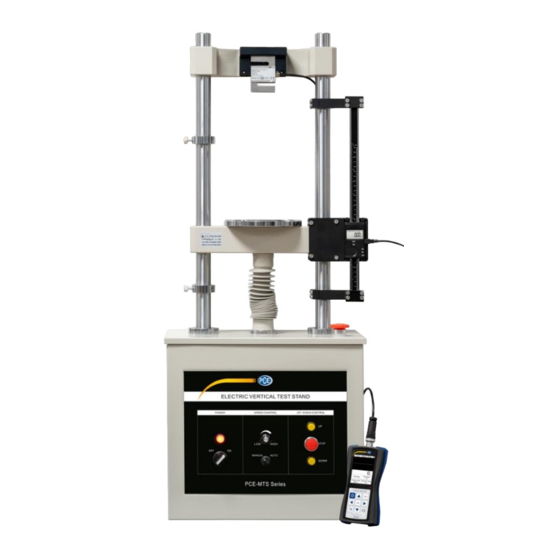
Kraft-Weg-Diagramme und Verläufe erstellen. Die im Lieferumfang enthaltene Software bietet dem Nutzer eine optimierte Oberfläche, um Diagramme und Graphen auswerten zu können. So lassen sich Materialprüfungen mit Kräften bis zu 5000 N (500 kg) realisieren. Wegmesssystem © PCE Instruments... -
Page 9: Messeinheit
Messeinheit Display Taste ON/OFF Taste ZERO Taste HOLD Taste ABS Taste mm/in Die Funktion der Tasten wird in der bei der Software beigelegten Bedienungsanleitung zur Benutzung des Gesamtsystems näher erläutert. © PCE Instruments... -
Page 10: Montage
Vollständigkeit. Eine Tabelle aller Bauteile finden Sie in Kapitel 2.2 Lieferumfang. Montage der Messgerätaufnahme Verschrauben Sie Bauteil (1) und Bauteil (3) mit Hilfe von zwei Schrauben (Bauteil 10). Montieren Sie die Madenschrauben (Bauteile 11 + 12) vor. © PCE Instruments... - Page 11 Stecken Sie die bisher montierte Baugruppe auf die Traverse Ihres PCE-MTS 500 Messstandes. Stecken Sie die Bauteile (4) in die Nut von Bauteil (1) und fixieren Sie diese locker mit Hilfe von zwei Schrauben (Bauteil 10). NICHT FIXIEREN / NUR LOCKER ANZIEHEN © PCE Instruments...
- Page 12 Nehmen Sie Bauteil (2) zur Hand und schrauben Sie dieses von hinten mit 4 Schrauben (Bauteil 10) an die Baugruppe. Achten Sie darauf, dass die Bauteile (4) in der Nut von Bauteil (2) sitzen. Schrauben Sie auch hier die an den Bauteilen (4) sitzenden Schrauben noch nicht fest. NICHT FIXIEREN NICHT FIXIEREN © PCE Instruments...
- Page 13 Stecken Sie nun oberhalb der Baugruppe das Bauteil (5) auf den Holm des PCE-MTS 500 Messstandes, setzen Sie Bauteil (6) an das Bauteil (5) an und fixieren Sie beide Bauteile mit Schrauben (Bauteil 9). Fixieren Sie Bauteil (7) mit den Schrauben (Bauteil 10) an Bauteil (5). © PCE Instruments...
- Page 14 Gehen Sie nun unterhalb der Baugruppe (1) gleichermaßen vor, sodass die Baugruppe wie folgt am PCE-MTS 500 Messstand angebracht ist. Außerdem schieben Sie die beiden Bauteile (4) gegen den Holm und fixieren Sie nun die vorfixierten Schrauben. © PCE Instruments...
-
Page 15: Integration Des Messgerätes In Die Baugruppe
Integration des Messgerätes in die Baugruppe Setzen Sie die Messeinheit (Bauteil 8) in die Baugruppe ein. Schieben Sie den unteren Halter und den oberen Halter auf die Enden des Messgerätes und fixieren Sie alle Schrauben (Befestigung an Holm und Messgerät). © PCE Instruments... - Page 16 Arretieren Sie nun die Messeinheit mit Hilfe der vormontierten Madenschrauben, sodass die Messeinheit vertikal arretiert ist. Das PCE-DFG FD 300 ist nun einsatzbereit und kann, wie in der Bedienungsanleitung beschrieben, verwendet werden. © PCE Instruments...
-
Page 17: Garantie
Zur Umsetzung der ElektroG (Rücknahme und Entsorgung von Elektro- und Elektronikaltgeräten) nehmen wir unsere Geräte zurück. Sie werden entweder bei uns wiederverwertet oder über ein Recyclingunternehmen nach gesetzlicher Vorgabe entsorgt. Alternativ können Sie Ihre Altgeräte auch an dafür vorgesehenen Sammelstellen abgeben. WEEE-Reg.-Nr.DE69278128 © PCE Instruments... -
Page 18: Safety Notes
We expressly point to our general guarantee terms which can be found in our general terms of business. If you have any questions, please contact PCE Instruments. The contact details can be found at the end of this manual. Safety symbols Safety-related instructions the non-observance of which can cause damage to the device or personal injury carry a safety symbol. -
Page 19: Specifications
Delivery scope 1 x bracket (consisting of 11 components) 1 x mounting kit (consisting of 24 screws and 2 set screws) 1 x measuring system 1 x data cable 1 x USB pen drive with PCE-DFG FD software © PCE Instruments... - Page 20 16 x © PCE Instruments...
-
Page 21: Optionales Accessories
PCE-DFG N 5K and on the mounting plate of the PCE-MTS 500 by means of the adaptor. In this way, flat tensile specimens can be integrated into the test setup in a very uncomplicated way. © PCE Instruments... -
Page 22: System Description
(e. g. PCE-DFG N 5K). With this add-on, force-path diagrammes and curves can be created. The included software provides you with an optimised interface for evaluating diagrammes and graphs. This allows material tests with forces of up to 5000 N (500 kg) to be conducted. Path measuring system © PCE Instruments... -
Page 23: Measuring Module
Measuring module Display ON/OFF key ZERO key HOLD key ABS key mm/in key The function of the keys is explained in more detail in the user manual for the complete system which comes with the software. © PCE Instruments... -
Page 24: Assembly
PCE-MTS 500 test stand. First check the delivery scope for completeness. A list of all components can be found in chapter 2.2 Delivery scope. Assembling the bracket for the meter Attach component (1) to component (3) using two screws (component 10). Pre-mount the set screws (components 11 + 12). © PCE Instruments... - Page 25 Attach the previously mounted module to the crossbeam of your PCE-MTS 500 test stand. Insert the components (4) into the groove of component (1) and fix them loosely with the help of two screws (component 10). DO NOT FIX ONLY TIGHTEN LOOSELY © PCE Instruments...
- Page 26 Screw component (2) onto the module from the back with 4 screws (component 10). Make sure that the components (4) are properly placed in the groove of component (2). Again, do not yet fix the screws on components (4). DO NOT FIX DO NOT FIX © PCE Instruments...
- Page 27 Now place component (5) on the rail of the PCE-MTS 500 test stand, above the module, attach component (6) to component (5) and fix both components with screws (component 9). Attach component (7) to component (5) with the screws (component 10).. © PCE Instruments...
- Page 28 Now proceed in the same way below module (1) so that the module is attached to the PCE-MTS 500 test stand as follows. In addition, slide the two components (4) against the rail and fix the pre-fastened screws. © PCE Instruments...
-
Page 29: Integration Of The Meter Into The Module
Integration of the meter into the module Insert the measuring module (component 8) into the assembled module. Slide the lower holder and the upper holder onto the ends of the meter and tighten all screws (attachment to the rail and meter). © PCE Instruments... - Page 30 Now lock the measuring module vertically with the help of the pre-mounted set screws. The PCE-DFG FD 300 is now ready for use and can be used as described in the user manual. © PCE Instruments...
-
Page 31: Warranty
For countries outside the EU, batteries and devices should be disposed of in accordance with your local waste regulations. If you have any questions, please contact PCE Instruments. © PCE Instruments... - Page 32 PCE Instruments contact information Germany France Spain PCE Deutschland GmbH PCE Instruments France EURL PCE Ibérica S.L. Im Langel 26 23, rue de Strasbourg Calle Mayor, 53 D-59872 Meschede 67250 Soultz-Sous-Forets 02500 Tobarra (Albacete) Deutschland France España Tel.: +49 (0) 2903 976 99 0 Téléphone: +33 (0) 972 3537 17...
- Page 33 User manuals in various languages (français, italiano, español, português, nederlands, türk, polski, русский, 中文) can be found by using our product search on: www.pce-instruments.com Specifications are subject to change without notice. © PCE Instruments...
Need help?
Do you have a question about the PCE-MTS Series and is the answer not in the manual?
Questions and answers