Table of Contents
Advertisement
Quick Links
Statement:
This manual is the intellectual property of Foxconn, Inc. Although the
information in this manual may be changed or modified at any time,
Foxconn does not obligate itself to inform the user of these changes.
Trademark:
All trademarks are the property of their respective owners.
Version:
User's Manual V1.0 for P4M8907MA motherboard.
Symbol description:
Note: refers to important information that can help you to use motherboard
better.
Attention: indicates that it may damage hardware or cause data loss,
and tells you how to avoid such problems.
Warning: means that a potential risk of property damage or physical
injury exists.
More information:
If you want more information about our products, please visit Foxconn's
website:
http://www.foxconnchannel.com
This product and its accessories are produced after 13th Aug, 2005 and comply
with the WEEE2002/96EC directive.
Advertisement
Table of Contents

Related Manuals for Foxconn P4M8907MA


Summary of Contents for Foxconn P4M8907MA
- Page 1 This manual is the intellectual property of Foxconn, Inc. Although the information in this manual may be changed or modified at any time, Foxconn does not obligate itself to inform the user of these changes. Trademark: All trademarks are the property of their respective owners.
- Page 2 HON HAI PRECISION INDUSTRY COMPANY LTD 66 , CHUNG SHAN RD., TU-CHENG INDUSTRIAL DISTRICT, TAIPEI HSIEN, TAIWAN, R.O.C. declares that the product Motherboard P4M8907MA is in conformity with (reference to the specification under which conformity is declared in accordance with 89/336 EEC-EMC Directive) þ...
- Page 3 Declaration of conformity Trade Name: Foxconn P4M8907MA Model Name: Industry Inc. Responsible Party: Address: 458 E. Lambert Rd. Fullerton, CA 92835 Telephone: 714-738-8868 Facsimile: 714-738-8838 Equipment Classification: FCC Class B Subassembly Type of Product: Motherboard Manufacturer: HON HAI PRECISION INDUSTRY...
-
Page 4: Table Of Contents
Table of Contents Chapter Product Introduction Main Features ..................... 2 Layout ......................4 Rear Panel Ports ..................5 Installation Instructions Chapter CPU ......................7 Memory ....................10 Power Supply................... 11 Other Connectors ..................12 Expansion Slots ..................16 Jumpers ....................17 Chapter BIOS Description Enter BIOS Setup .................. - Page 5 Table of Contents Chapter Driver CD Introduction Utility CD content ..................52 Installing Drivers ..................53 Installing Utilities ..................53 Chapter Directions for Bundled Software FOX ONE ....................55 Fox LiveUpdate ..................61...
- Page 6 Attention: 1. Attach the CPU and heatsink using silica gel to ensure full contact. 2. It is suggested to select high-quality, certified fans in order to avoid damage to the motherboard and CPU due high temperatures. 3. Never turn on the machine if the CPU fan is not properly installed. 4.
- Page 7 This manual is suitable for motherboard of P4M8907MA. Each motherboard is carefully designed for the PC user who wants diverse features. -L with onboard 10/100M LAN (Default is omitted) -K with onboard Gigabit LAN -6 with 6-Channel audio (Default is omitted)
-
Page 8: Main Features
Chapter Thank you for your bu ying Foxconn P4M8907MA series motherboard. This series of motherboard is one of our new products and offers superior performance, reliability and quality, at a reasonable price. This motherboard adopts the advanced VIA P4M890 + VT8237R Plus chipsets, providing users a computer platform with a high integration-com- patibility-performance price ratio. - Page 9 Chapter 1 Product Introduction Main Features Size · mATX form factor of 9.6” x 8.81” Microprocessor ® ® ® ® ® · Supports Intel Pentium 4 Extreme Edition, Pentium D, Pentium 4, Celeron D processors in an LGA775 package · Supports FSB 1066MHz/800MHz/533MHz CPU Chipsets ·...
- Page 10 Chapter 1 Product Introduction Onboard Audio · AC’ 97 2.3 Specification Compliant · Supports S/PDIF output · Onboard Line-in jack, Microphone jack, Line-out jack · Supports 6-channel audio Onboard Graphics · Supports VGA display function (S3 Graphics UniChrome Pro IGP) Expansion Slots ·...
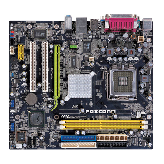
- Page 11 Chapter 1 Product Introduction Motherboard Layout 1. S/PDIF OUT Connector 14.SATA Connectors 2. Front Audio Connector 15.HDD Connectors 3. CD_IN Connector 16.FDD Connector 4. AUX_IN Connector 17.24-pin ATX Power Connector 5.PCI Express X1 slot 18.DDR 2 memory Slots 6.Speaker Connector 19.CPU Fan Connector 7.
- Page 12 Chapter 1 Product Introduction Rear Panel Ports This motherboard provides the ports as below: Parallel Port LAN Port (Printer Port) Line-in jack PS/2 Mouse Port Line-out jack PS/2 Keyboard Microphone jack Port Serial Port VGA Port USB 2.0 Ports (COM1) Use the three audio ports to connect audio devices.
-
Page 13: Chapter 2 Installation Instructions
Chapter 2 Installation Instructions Chapter This chapter introduces the hardware installation process, including the installation of the CPU and memory. It also addresses the connection of your power supply, connec- tion of hard drive and floppy drive data cables, and setting up various other feature of the motherboard. - Page 14 Chapter 2 Installation Instructions ® ® ® This motherboard supports Intel Pentium 4 Extreme Edition,Pentium ® ® Pentium 4, Celeron D processor in an LGA775 package. For the detailed CPU support list on this motherboard, please visit the website: http://www.foxconnchannel.com Installation of CPU Below is the CPU socket illustration.
- Page 15 Chapter 2 Installation Instructions 3. Hold CPU with thumb and forefinger. Ensure fingers align to socket cutouts. Match the CPU triangle marker to Pin 1 position as shown below. The alignment key also provides the orientation directed function. Lower the CPU straight down without tilting or sliding the CPU in the socket.
- Page 16 Chapter 2 Installation Instructions 5. Close the load plate, and slightly push down the tongue side. 6. Lower the lever and lock it to the load plate, then the CPU is locked completely. Note : Excessive temperatures will severely damage the CPU and system.
- Page 17 Chapter 2 Installation Instructions Memory This motherboard includes two 240-pin slots for DDR2. You must install at least one memory module to ensure normal operation. Mixed memory modules from different manufacturers is not recommended. Installation of DDR2 Memory 1. There is only one gap near the center of the DIMM slot, and the memory module can be fixed in one direction only.
- Page 18 Chapter 2 Installation Instructions Power Supply This motherboard uses an ATX power supply. In order to avoid damaging any devices, make sure that they have been installed properly prior to connecting the power supply. 24-pin ATX Power Connector +5V_AUX 24-pin ATX power connector: PWR1 +3.
- Page 19 Chapter 2 Installation Instructions Other Connectors This motherboard includes connectors for FDD devices, IDE devices, Serial ATA devices, USB devices, IR module, and others. FDD Connector: FLOPPY This motherboard includes a standard FDD connector, supporting 360K, 720K, 1.2M, 1.44M, and 2.88M FDDs. HDD Connectors: PIDE &...
- Page 20 Chapter 2 Installation Instructions Front Panel Connector: FP1 This motherboard includes one connector for connecting the front panel switch and LED indicators. PL ED PW RBT N# HDD_LED R E S E T Hard Disk LED Connector (HDD_LED) The connector connects to the case’s IDE indicator LED indicating the activity status of IDE hard disk.
- Page 21 Chapter 2 Installation Instructions IrDA Connector: IR This connector supports wireless transmitting E m p t y and receiving device. Before using this function, configure the settings of IR Address, IR Mode and IR IRQ from the “Integrated Peripherals” section of the CMOS Setup. USB Connectors: F_USB1, F_USB2 Besides four USB ports on the rear panel, the series of motherboards also have two 10-pin...
- Page 22 Chapter 2 Installation Instructions S/PDIF Out Connector: SPDIF_OUT +5 V The S/PDIF out connector is capable of provid- Empty ing digital audio to external speakers or com- S PD I F _ O UT pressed AC3 data to an external Dolby digital SPDIF_OUT decoder.
- Page 23 Chapter 2 Installation Instructions Expansion Slots This motherboard includes two 32-bit master PCI slots, one PCI Express x 1 slot, and one PCI Express x 16 slot. PCI Slots The expansion cards can be installed in the two PCI slots. PCI slots support cards such as a LAN card, USB card, SCSI card and other cards that comply with PCI specifications.
-
Page 24: Jumpers
Chapter 2 Installation Instructions Jumpers The users can change the jumper settings on this motherboard if needed. This sec- tion explains how to use the various functions of this motherboard by changing the jumper settings. Users should read the following contents carefully prior to modifying any jumper settings. - Page 25 Chapter 2 Installation Instructions BIOS protection Jumper: WP_EN (optional) CLOSED If the jumper WP_EN is set as OPEN, the system Disabled BIOS is protected from being attacked by a serious virus, such as the CIH virus. You will be unable to OPEN flash the BIOS to the motherboard, when the sys- Enabled...
-
Page 26: Chapter 3 Bios Description
Chapter 3 BIOS Description Chapter This chapter tells how to change system settings through the BIOS Setup menus. Detailed descriptions of the BIOS param- eters are also provided. You have to run the Setup Program when the following cases occur: 1. -
Page 27: Enter Bios Setup
Chapter 3 BIOS Description Enter BIOS Setup The BIOS is the communication bridge between hardware and software, correctly setting up the BIOS parameters is critical to maintain optimal system performance. Power on the computer, when the following message briefly appears at the bottom of the screen during the POST (Power On Self Test), press <Del>... - Page 28 Chapter 3 BIOS Description Advanced BIOS Features The advanced system features can be set up through this menu. Advanced Chipset Features The values for the chipset can be changed through this menu, and the sys- tem performance can be optimized. Integrated Peripherals All onboard peripherals can be set up through this menu.
-
Page 29: Standard Cmos Features
Chapter 3 BIOS Description Standard CMOS Features This sub-menu is used to set up the standard CMOS features, such as the date, time, HDD model and so on. Use the arrow keys select the item to set up, and then use the <PgUp> or <PgDn> keys to choose the setting values. Standard CMOS Features Menu Date This option allows you to set the desired date (usually as the current day) with... - Page 30 Chapter 3 BIOS Description Award (Phoenix) BIOS can support 3 HDD modes: CHS, LBA and Large or Auto mode. For HDD<528MB For HDD>528MB & supporting LBA (Logical Block Addressing) Large For HDD>528MB but not supporting LBA Auto Recommended mode Drive A This option allows you to select the kind of FDD to be installed, including “None”, [360K, 5.25 in], [1.2M, 5.25 in], [720K, 3.5 in], [1.44M, 3.5 in] and [2.88 M, 3.5 in].
- Page 31 Chapter 3 BIOS Description Memory This is a Display-Only Category, determined by POST (Power On Self Test) of the BIOS. Base Memory The BIOS POST will determine the amount of base (or conventional) memory installed in the system. Extended Memory The BIOS determines how much extended memory is present during the POST.
-
Page 32: Fox Central Control Units
Chapter 3 BIOS Description FOX Central Control Unit FOX Central Control Unit Menu v[Smart BIOS] Smart Power LED Smart debug LED function within power LED. Enable this function, the power LED status can show the system status of POST process. System Status Power LED Status Normal... - Page 33 Chapter 3 BIOS Description vSpread Spectrum If you enable spread spectrum, it can significantly reduce the EMI(Electro- Magnetic Interference) generated by the system. The setting values are Dis- abled and Enabled. vCPU Clock This option is used to set the CPU clock. vDRAM Clock/Driver Control Press Enter to set the items of DRAM Clock/Driver Control.
- Page 34 Chapter 3 BIOS Description DRAM Clock/Drive Control Menu v1T CMD Support This option is used to set whether the first command delay of 1 clock cycle is enable. vCurrent FSB/DRAM Frequency This option is used to show current FSB and DRAM Frequency. vDRAM Clock This option is used to set DRAM clock.
- Page 35 Chapter 3 BIOS Description vPrecharge to Active (Trp) This option controls the number of cycles for Row Address Strobe (RAS) to be allowed to precharge. If insufficient time is allowed for the RAS to accumulate its charge before DRAM refresh, refresh may be incomplete and DRAM may fail to retain data.
-
Page 36: Advanced Bios Features
Chapter 3 BIOS Description Advanced BIOS Features Advanced BIOS Features Menu vCPU Feature Press enter to set the items of CPU feature. vHard Disk Boot Priority This option is used to select the priority for HDD startup. After pressing <Enter>, you can select the HDD using the <PageUp>/<PageDn> or Up/Down arrow keys, and change the HDD priority using <+>... - Page 37 Chapter 3 BIOS Description vFirst/Second/Third Boot Device This option allows you to set the boot device sequence. The available setting values are: Floppy, LS120, Hard Disk, CDROM, ZIP100, USB-FDD, USB-ZIP, USB-CDROM, Legacy LAN, NVIDIA Boot Age and Disabled. vBoot Other Device W ith this item enabled, the system will search all other possible locations if it fails to find one in the devices specified under the first, second and third boot devices.
- Page 38 Chapter 3 BIOS Description vOS Select For DRAM > 64MB This option is only required if you have installed more than 64 MB of memory and you are running the OS/2 operating system. Otherwise, leave this option at the default. vDelay For HDD(Secs) This option is used to set delay boot time of HDD controller.
- Page 39 Chapter 3 BIOS Description CPU Feature Menu Delay Prior to Thermal This option is used to set the delay time before the CPU enters auto thermal mode. The setting values are: 4 Min, 8 Min, 16 Min, 32 Min. vThermal Management This option is used to manage Prescott CPU thermal.
-
Page 40: Advanced Chipset Features
Chapter 3 BIOS Description Advanced Chipset Features Advanced Chipset Features Menu vAGP & P2P Bridge Control Press enter to set the items about AGP & P2P bridge. vCPU & PCI Bus Control Press enter to set the items about CPU & PCI bus. vMemory Hole This option is used to select memory hole. - Page 41 Chapter 3 BIOS Description AGP & P2P Bridge Control Menu vAGP Aperture Size This option defines the size of the aperture if you use an AGP graphics adapter. The aperture is a portion of the PCI memory address range dedicated for graphic memory address space.
- Page 42 Chapter 3 BIOS Description CPU & PCI Bus Control Menu vPCI Master 0 WS Write This option allows you to enable or disable the support of PCI Master 0 W ait State W rite. The setting values are: Disabled and Enabled. vPCI Delay Transaction This option allows you to enable or disable PCI delay transaction.
-
Page 43: Integrated Peripherals
Chapter 3 BIOS Description Integrated Peripherals Integrated Peripherals Menu vVIA OnChip IDE Device Press enter to set onchip IDE device. vVIA OnChip PCI Device Press enter to set onchip PCI device. vSuperIO Device Press enter to set onboard SuperIO device. vOnboard Lan Device This option is used to enable or disable onboard LAN device. - Page 44 Chapter 3 BIOS Description VIA OnChip IDE Device Menu OnChip SATA This option is used to enable or disable onchip SATA. The setting values are: Disabled and Enabled. vSATA Mode This option is used to select SATA mode. The setting values are: IDE and RAID.
- Page 45 Chapter 3 BIOS Description VIA OnChip PCI Device Menu vVIA-3058 AC97 Audio “Auto” allows the motherboard’s BIOS to detect whether you’re using any audio devices. If so, the onboard audio controller will be enabled. If not, the onboard audio controller will be disabled. If you want to use different control- ler cards to connect audio connectors, set the option to “Disabled”.
- Page 46 Chapter 3 BIOS Description SuperIO Device Menu vOnboard FDC Controller This option is used to set whether the Onboard FDC Controller is enabled. The available setting values are: Disabled and Enabled. vOnboard Serial Port1/2 This option is used to assign the I/O address and interrupt request (IRQ) for the onboard serial port 1/2.
-
Page 47: Power Management Setup
Chapter 3 BIOS Description Power Management Setup Power Management Setup Menu vACPI function ACPI stands for “Advanced Configuration and Power Interface”. ACPI is a standard that defines power and configuration management interfaces be- tween an operating system and the BIOS. In other words, it is a standard that describes how computer components work together to manage system hardware. - Page 48 Chapter 3 BIOS Description vSuspend Mode This option is used to set the idle time before the system enters into sleep status. The setting values are: Disabled, 1 Min, 2 Min, 4 Min, 6 Min, 8 Min, 12 Min, 20 Min, 30 Min, 40 Min, 1 Hour. vVideo Off Option This option is used to set video off option.
- Page 49 Chapter 3 BIOS Description IRQ/Event Activity Detect Menu vPS2KB Wakeup Select This option is used to select which action will wake up PS/2 keyboard from S3 /S4/S5 staus. Use <PgUp> or <PgDn> to select the desired item. vPS2KB Wakeup from S3/S4/S5 This option is used to select which hotkey will wake up by PS/2 keyboard from S3/S4/S5 staus or disable it.
- Page 50 Chapter 3 BIOS Description vPowerOn by PCI Card This option is used to set whether the system is wakeuped by PCI Card.If “Enabled” any PCI interrupt will wake up the system. vModem Ring Resume This option is used to set the system to be waked up by the modem ring. vRTC Alarm Resume This option is used to set alarm to power on the system by the date (1-31) or time (hh:mm:ss).
- Page 51 Chapter 3 BIOS Description IRQs Activity Monitoring Menu Primary INTR Selecting “ON” will cause the system to wake up from power saving modes if activity is detected from any enabled IRQ channels. The setting values are: ON and OFF. vIRQ3 (COM2) This option is used to enable or disable IRQ3 (COM2) activity monitoring.
- Page 52 Chapter 3 BIOS Description vIRQ11 (Reserved) This option is used to enable or disable IRQ11 (Reserved) activity monitoring. The setting values are: Disabled and Enabled. vIRQ12 (PS/2 Mouse) This option is used to enable or disable IRQ12 (PS/2 Mouse) activity monitoring. The setting values are: Disabled and Enabled.
-
Page 53: Pnp/Pci Configurations
Chapter 3 BIOS Description PnP/PCI Configurations PnP/PCI Configurations Menu PNP OS Installed Set this field to “Yes” if you are running W indows 95, which is PnP compatible. It is recommended to keep the default setting. vInit Display First This option is used to set which display device will be used first when your PC starts up. - Page 54 Chapter 3 BIOS Description vAssign IRQ For USB This option is used to set whether BIOS will assign IRQ for USB. vMaximum Payload Size This option is used to set maximum TLP payload size for PCI Express devices. The unit is byte.
-
Page 55: Pc Health Status
Chapter 3 BIOS Description PC Health Status PC Health Status Menu vCPU Warning Temperature This option is used to set the warning temperature for the system.W hen the temperature of CPU is higher than setting value, the motherboard will send out warning information. -
Page 56: Load Fail-Safe Defaults
Chapter 3 BIOS Description Load Fail-Safe Defaults Press <Enter> to select this option. A dialogue box will pop up that allows you to load the default BIOS settings. Select <Y> and then press <Enter> to load the defaults. Select <N> and press <Enter> to exit without loading. The defaults set by BIOS set the basic system functions in order to ensure system stability. -
Page 57: Save & Exit Setup
Chapter 3 BIOS Description If you do not want to set a password, just press <Enter> when prompted to enter a password, and in the screen the following message will appear. If no password is keyed in, any user can enter the system and view/modify the CMOS settings. Password Disabled!!! Press any key to continue …... -
Page 58: Chapter 4 Driver Cd Introduction
Chapter 4 Driver CD Introduction Chapter The utility CD that came with the motherboard contains use- ful software and several utility drivers that enhance the motherboard features. This chapter includes the following information: Utility CD content Installing Drivers Installing Utilities... -
Page 59: Utility Cd Content
Use this option to install additional software programs. A. FOX ONE B. Fox LiveUpdate C. Microsoft DirectX 9.0 D. Adobe Acrobat Reader E. Norton Security F. Create RAID Driver Floppy 3. Link to website Click static Foxconn Logo to visit our homepage. -
Page 60: Installing Drivers
Chapter 4 Driver CD Introduction Installing Divers There are two ways to install drivers, manual or auto. Click the drivers that you want to install and begin the setup steps by manual. Or you just click “One Click Setup” button to install the drivers by auto after install Intel Chipset Driver. Install by manual Install by auto Installing Utilities... - Page 61 Chapter 4 Driver CD Introduction Chapter This chapter will introduce how to use attached software. This chapter provides the following information: FOX ONE Fox LiveUpdate...
-
Page 62: Chapter 5 Directions For Bundled Software
Chapter 5 Directions for Bundled Software FOX ONE FOX ONE is a powerful utility for easily modifying system settings. It also allows users to monitor various temperature values, voltage values, frequency and fan speed at any time. With FOX ONE, you can -Modify system performance settings, such as bus speeds, CPU voltages, fan speed, and other system performance options that are supported by the BIOS... - Page 63 Click this button to configurate the parameters for the program. It determines which items will be shown in shorten mode. Homepage Click this button to visit Foxconn motherboard website. 2. CPU Page - CPU Control This page lets you select and run the FOX ONE developed benchmarks to determine the current performance level of the system.
- Page 64 Chapter 5 Directions for Bundled Software Go to CPU page Close this page Ajust by manual Reset the Apply the changes changes Select the different benchmarks 3. Freq. Page - Frequency Control This page lets you set memory and PCI Express frequency by manual. Go to Freq.
- Page 65 Chapter 5 Directions for Bundled Software 4.1 Limit Setting - CPU Temp. This page lets you to set CPU high limit temperature and enable the alert function. Show current CPU Go to Adjust page temperature value Enable alert function when the CPU temperature is higher than high limit value Show current high...
- Page 66 Chapter 5 Directions for Bundled Software 4.3 Limit Setting - CPU Fan This page lets you to set CPU fan low limit rpm and enable the alert function. Show current CPU fan rpm value Enable alert function when the CPU fan rev is lower than low limit rpm value Show current low limit...
- Page 67 Chapter 5 Directions for Bundled Software 4.5 Limit Setting - Chassis Fan This page lets you to set chassis fan low limit rpm and enable the alert function. Show current Chassis fan rpm value Enable alert function when the chassis fan is lower than low limit rpm value Show current low limit rpm value of chassis fan...
-
Page 68: Fox Liveupdate
Chapter 5 Directions for Bundled Software Fox LiveUpdate Fox LiveUpdate is a useful utility for backuping and updating the system BIOS, drivers and utilities by local or online. Supported Operating Systems: -W indows 2000 -Windows XP (32-bit and 64-bit) -W indows 2003 (32-bit and 64-bit) Using Fox LiveUpdate: 1.1 Local Update - BIOS Info. - Page 69 Chapter 5 Directions for Bundled Software 1.2 Local Update - Backup This page lets you backup your system BIOS. Click “Backup”, then give a name. Click “Save” to finish the backup operation. Key in a BIOS name Click here 1.3 Local Update - Update This page lets you update your system BIOS from Internet.
- Page 70 Chapter 5 Directions for Bundled Software 2.1 Online Update - Update BIOS This page lets you update your system BIOS from Internet. Click “start”, it will search the new BIOS from Internet. Then follow the wizard to finish the update operation.
- Page 71 Chapter 5 Directions for Bundled Software 2.2 Online Update - Update Driver This page lets you update your system drivers from Internet. Click “start”, it will search the new drivers from Internet. Then follow the wizard to finish the update operation.
- Page 72 Chapter 5 Directions for Bundled Software 2.3 Online Update - Update Utility This page lets you update utilities from Internet. Click “start”, it will search the new utilities from Internet. Then follow the wizard to finish the update operation. Click here Current information Search new utilities from Internet...
- Page 73 Chapter 5 Directions for Bundled Software 3.1 Configure - option This page lets you set auto search options. After your setting, the utility will start searching and related information will show on the task bar. Click here Set auto search options Select search which kind of versions...
- Page 74 Chapter 5 Directions for Bundled Software 3.2 Configure - System This page lets you set the backup BIOS location and change different skin of the utility. Click here Set the location of download files or auto backup BIOS Select different skin of the software Determine if the Fox Apply the changes...
Need help?
Do you have a question about the P4M8907MA and is the answer not in the manual?
Questions and answers