
Summary of Contents for Blue Ice Azzurri Classico CM632
- Page 1 www.blueicecreammachine.co.uk Intelligent Fresh Ground Coffee Machine Service Manual...
- Page 3 KLM1601 AZZURRI CLASSICO Intelligent Fresh Ground Coffee Machine Service Manual English...
-
Page 4: Table Of Contents
Contents Contents 1. Introduction General warnings Symbol description 2. Structure 2.1 Overview 2.2 Description of internal components 2.3 Water circuit 2.3.1 Overview of water circuit 2.3.2 Water circuit for making coffee 2.3.3 Water circuit for making steam 2.3.4 Water circuit for making hot water 2.4 Schematic circuit diagram 2.5 Technical data 3. - Page 5 Contents 4.2.15 Disassemble thermoblock group 4.2.16 Disassemble ground coffee container lid switch group 4.3 Precautions for maintenance and installation 4.3.1 Brew unit group 4.3.2 Dispenser valve 6W 4.3.3 Grinder group 4.3.4 Control panel group Precautions for assembling 5. Function test and maintenance 5.1 Function test and test standards 5.2 Coffee machine maintenance 5.2.1 Coffee machine decalcifying...
-
Page 6: Introduction
Introduction 1. Introduction The manufacturer reserves the right to make product improvements. We guarantee that this manual respects the technological status at the time the machine is supplied. We are open to any suggestions from technicians which may improve the product and the manual. General warnings Once the packaging has been removed make sure the appliance is in good condition;... -
Page 7: Symbol Description
Introduction Symbol description Non-compliance with the operation, may cause electric shock, and threat to life. Non-compliance with the operation may cause coffee machine damaged, or personal injury. Non-compliance with the operation, may cause scalded or burned. This symbol, if prompted, please carefully read information with it. -
Page 8: Structure
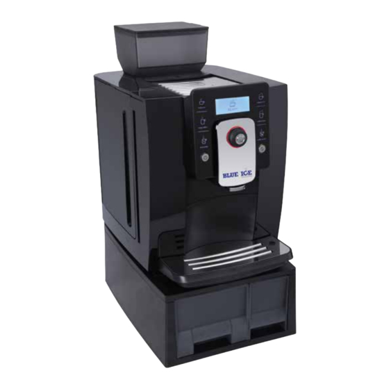
Structure 2. Structure 2.1 Overview Bean container lid Front cover right Top cover Touch screen Water tank cover Rotary Water tank ornament cover Clean button Water tank Decorative plate Support elect Handle Power button Drip tray decoration cover Front cover left Drip tray cover Cup support Drip tray... - Page 9 Structure Bean container Grinder adjustment knob Ground coffee container lid Hot water export Coffee export Milk connector Foam rubber Light for coffee Milk and foam export Back cover Logo Right side section Left side section Power line www.blueicecreammachine.co.uk...
-
Page 10: Description Of Internal Components
Structure 2.2 内部组件说明 Thermoblock Dispenser valve 3W Geared motor Dispenser valve 2W Dispenser valve Condensator Support PCBA Pump Drainage valve Line pencil connector Transformer Base Brew unit Solenoid valve Drip tray microswitch Reed sensor Flowmeter Valve support Control panel Grinder group KLM1601 AZZURRI CLASSICO Intelligent Fresh Ground Coffee Machine... -
Page 11: Water Circuit
Structure 2.3 Water circuit 2.3.1 Overview of water circuit Water tank Coffee thermoblock Sieve Dispenser valve 2W Flowmeter Drainage valve Condensator Brew unit Pump Beverage export Pressure maintaining valve Reversing valve Steam thermoblock Solenoid valve Dispenser valve 3W www.blueicecreammachine.co.uk... -
Page 12: Water Circuit For Making Coffee
Structure 2.3.2 Water circuit for making coffee Valve support Coffee thermoblock Flowmeter Dispenser valve 2W Condensator Drainage valve Pump Brew unit Dispenser valve 3W Export AZZURRI CLASSICO KLM1601 Intelligent Fresh Ground Coffee Machine Service Manual... -
Page 13: Water Circuit For Making Steam
Structure 2.3.3 Water circuit for making steam Valve support Steam thermoblock Flowmeter Dispenser valve Condensator Solenoid valve Pump Foam rubber Dispenser valve 3W www.blueicecreammachine.co.uk... -
Page 14: Water Circuit For Making Hot Water
Structure 2.3.4 Water circuit for making hot water Valve support Dispenser valve 3W Flowmeter Coffee thermoblock Condensator Dispenser valve Pump Export KLM1601 AZZURRI CLASSICO Intelligent Fresh Ground Coffee Machine Service Manual... -
Page 15: Schematic Circuit Diagram
Structure 2.4 Schematic circuit diagram Coffee Lamp Milk Bin Water Flow BinWater Power Steam Coffee Brew Coffee Step Steam Power switch Coffee fused-cord OLED screen Steam fused-cord Pump Rotary PCB Grinder motor Terminal Feedback device LED×2 Microswitch Valve Stepper motor Reed sensor Motor for dispenser valve Drip tray microswitch... -
Page 16: Technical Data
Structure 2.5 Technical data Total voltage/power China 220V/50HZ 1200W Europe 230V/50HZ 1400W Approvals CCC,CB,GS,CE Power ratings Thermoblock 220V 1200W Pump 230V/50HZ 48W ULKA EP4 Grinder motor DC 220V Drive motor DC 24V Dispenser valve motor DC 24V Solenoid valve DC 24V Capacities Water tank 1.8L... -
Page 17: Troubleshooting
Contents 4.2.15 Disassemble thermoblock group 4.2.16 Disassemble ground coffee container lid switch group 4.3 Precautions for maintenance and installation 4.3.1 Brew unit group 4.3.2 Dispenser valve 6W 4.3.3 Grinder group 4.3.4 Control panel group Precautions for assembling 5. Function test and maintenance 5.1 Function test and test standards 5.2 Coffee machine maintenance 5.2.1 Coffee machine decalcifying... - Page 18 Troubleshooting Prob- Item Confirmation Problem Cause Remedy Remarks ability Wrong installation YES - confirm if the rubber foam 3.2.4.1 for foam rubber installed correct group NO - continue to 3.2.4.2 Foam rubber can 3.2.4 not be Replace or repair installed damaged parts Foam rubber is YES - replace 79000054 or...
- Page 19 Troubleshooting Prob- Item Confirmation Problem Cause Remedy Remarks ability 1. Disassemble control The connector panel according to YES - connect or repair power between PCB and 4.2.8; switch connector 3.3.1.5 powder switch 2. Disassemble control NO - continue to 3.3.1.6 does not work panel,repair connection line according to 4.3.4...
- Page 20 Troubleshooting Prob- Item Confirmation Problem Cause Remedy Remarks ability Disassemble PCBA, FILL WATER YES - replace or repair PCBA, PCBA damaged replace and repair 3.3.2.8 TANK on 3.3.2 item: 78000006 according to 4.2.12 screen Lots of coffee YES - clean rest coffee powder 3.3.3.1 powder left on the NO - continue to 3.3.3.2...
- Page 21 Troubleshooting Prob- Item Confirmation Problem Cause Remedy Remarks ability Inside pipe connector YES - repair damaged pipe or damaged- water connector 3.3.5.2 leakage(lots of NO - continue to 3.3.5.3 water on the table) 1. Disassemble drainage valve group according to 4.2.10; YES - replace drainage valve Drainage valve 2.
- Page 22 Troubleshooting Prob- Item Confirmation Problem Cause Remedy Remarks ability 1. Disassemble brew unit according to 4.2.3; YES - replace brew unit seal, item: 2. Replace or repair Contropistone seal 3.3.6.4 73000065 damaged components damaged NO - continue to 3.3.6.5 according to brew unit explosive view Little water 8810101016...
- Page 23 Troubleshooting Prob- Item Confirmation Problem Cause Remedy Remarks ability 1. Disassemble control panel according to 4.2.8; 2. Disassemble control panel components Rotary is stucked YES - replace rotary, according to 4.3.4; 3.4.2.1 so it can not be item: 79000058 3. Replace or repair moved or pressed NO - continue to 3.4.2.2 damaged components...
- Page 24 Troubleshooting Prob- Item Confirmation Problem Cause Remedy Remarks ability The following should be repaired by dismatling the machine Grinder group 1. Disassemble grinder YES - connect or replace motor teminal or group according to 4.2.7; 3.5.1.1 connection line, item: 78000020 connection line 2.
- Page 25 Troubleshooting Prob- Item Confirmation Problem Cause Remedy Remarks ability If conical burr and upper burr is stucked by YES - take out foreign object from foreign object, there will Grinder group is grinder group be different regular 3.5.2.9 stucked FILL BEANS NO - continue to 3.5.2.10 noise when the conical displays on...
- Page 26 Troubleshooting Prob- Item Confirmation Problem Cause Remedy Remarks ability 1. Disassemble brew unit Brew unit parts according to 4.2.3; No coffee damaged; when 2. Replace or repair comes out making coffee YES - replace damaged parts in 3.5.3 3.5.3.8 damaged components from coffee ,coffee brewing brew unit...
- Page 27 Troubleshooting Prob- Item Confirmation Problem Cause Remedy Remarks ability 1. Disassemble drainage Drainage valve valve group according group damaged, no water comes to to 4.2.10; YES - replace drainage valve 2. Replace or repair brew unit, 3.5.6.5 group damaged components dropped to drip NO - continue to 3.5.6.5 according to drainage...
- Page 28 Troubleshooting Prob- Item Confirmation Problem Cause Remedy Remarks ability YES - use Kalerm provided coffee Not enough spoon, fill one full spoon of coffee LACK OF 3.6.1.1 coffee powder powder POWDER NO - continue to 3.6.1.2 3.6.1 displays on the screen YES - open powder container Coffee powder 3.6.1.2...
- Page 29 Troubleshooting Prob- Item Confirmation Problem Cause Remedy Remarks ability 1. Disassemble dispenser valve according to 4.2.9; 2. Disassemble No water dispenser valve comes out Drainage YES - replace damaged drainage 3.7.1.4 according to 4.3.2; 3.7.1 from water damaged valve 3. Replace or repair export damaged components according to dispenser...
- Page 30 Troubleshooting Prob- Item Confirmation Problem Cause Remedy Remarks ability YES - clear or replace milk pipe Milk pipe clogged 3.10.1.3 NO - continue to 3.10.1.4 YES - clear or replace foam According to foam Foam rubber 3.10.1.4 rubber explosive view rubber, item: 79000187 clogged 881010022...
- Page 31 Troubleshooting Prob- Item Confirmation Problem Cause Remedy Remarks ability YES - replace valve, item: 73000057 3.11.2.3 Valve damaged Refer to 3.11.2.2 NO - continue to 3.11.2.4 It is milk instead of process to cream 3.11 3.11.2 YES - replace air pipe, make inside the 3.11.2.4...
- Page 32 Troubleshooting Prob- Item Confirmation Problem Cause Remedy Remarks ability System testing YES - Restart the machine 3.16.1.1 Malfunction NO - continue to 3.16.1.2 Coffee YES - repair or replace coffee According to explosive thermoblock thermoblock connection line; 3.16.1.2 view 8810101025 connection line fell item: 78000014 and 78000015 off or damaged...
- Page 33 Troubleshooting Prob- Item Confirmation Problem Cause Remedy Remarks ability ERROR 6 Dispenser valve press 5 YES - replace damaged parts Refer to 3.16.3.1 internal structure 3.16.3.4 times UNIT NO - continue to 3.16.3.5 damaged EMPTY, and it still can 3.16.3 not be Water circuit YES - repair or clear water circuit...
- Page 34 Troubleshooting Prob- Item Confirmation Problem Cause Remedy Remarks ability YES - replace motor, Dispenser valve 3.17.4.5 item: 73000010 Refer to 3.17.4.3 Error3 motor for damaged NO - continue to 3.17.4.6 (VALVE 3.17.4 RESET Dispenser valve RESTART 3.17.4.6 internal structure YES - replace damaged parts Refer to 3.17.4.3 damaged YES - restart the machine...
-
Page 35: Check List For Minor Failure
Troubleshooting 3.2 Check list for minor failure 3.2.1 Function 3.2.1.1 Reed sensor function If there is water in water tank, but the screen displays FILL WATER TANK,put a magnet in left side section as the picture shows: if the screen does not display FILL WATER TANK anymore- water tank components damaged- replace components;If the screen still displays FILL WATER TANK- internal line fault-... - Page 36 Troubleshooting 3.2.1.4 Press button Operation all the function buttons on the control panel to judge if the press buttons are all right,and confirm issues and causes according to check list 3.1. 3.2.2 Circuit 3.2.2.1 Check fuse inside line pencil connector If the fuse is damaged, machine can not be started on.
- Page 37 Troubleshooting 3.2.2.5 Check all switches The picture shows off-state. When touch microswitch contactor, it is on-state. 3.2.3. Leakage Take off drip tray layer board as the picture shows, fill drip tray microswitch with paper, and press rinse button Check leakage of brew unit www.blueicecreammachine.co.uk...
- Page 38 Troubleshooting Check leakage of connectors KLM1601 AZZURRI CLASSICO Intelligent Fresh Ground Coffee Machine Service Manual...
-
Page 39: Repair
Repair 4. Repair 4.1 Tools preparation Torx screwdriver(T6,T10,T15,T20,T25) Slotted type screwdriver (3mm series) Multimeter Needle-nose pliers Electronic scale Temperature tester www.blueicecreammachine.co.uk... -
Page 40: General Disassembly
Repair 4.2 Disassemble process for components 4.2.1 Disassemble exterior parts 4.2.1.1 Take out movable parts 1. Take out drip tray 2. Take out bean container lid group 3. Take out water tank group 4.2.1.2 Disassemble back cover 1. Rotate the Logo support according 2. - Page 41 Repair 3. Take out back cover according to the arrow direction 4.2.1.3 Disassemble front cover right and front cover left 1. Disassemble the 2 screws from 2. Take out front cover right and front the bottom cover left separately according to the direction of the arrow 4.2.1.4 Disassemble right cover 1.
- Page 42 Repair 4.2.1.5 Disassemble coffee bean container group 1. Disassemble 4 screws from the coffee bean container, and take the coffee bean container out 4.2.1.6 Disassemble top cover 1. Disassemble 2 screws from the left 2. Loose top cover and hook of the side of the top cover frame 3.
-
Page 43: Disassemble Power Cord
Repair 4.2.1.7 Disassemble left cover 1. Disassemble left side section according to the direction of the arrow 4.2.2 Disassemble power cord 1. Refer to 4.2.1- Disassemble the exterior parts of the machine 2. Disassemble 2 screws from the 3. Disassemble 1 screw from support, cable rack loose 3 screws inside the line pencil connector and take out the power cord... -
Page 44: Disassemble Brew Unit
Repair 4.2.3 Disassemble brew unit 1. Refer to 4.2.1- Disassemble exterior parts of the machine 2. Disassemble 3 screws, and take 3. Pull out silicon pipe from brew unit out frame support 4. Disassemble 3 screws from brew unit 5. Pull the brewing unit outward and 6. -
Page 45: Disassemble Valve Support Group
Repair 4.2.4 Disassemble valve support group 1. Refer to 4.2.1-disassemble exterior parts 2. Take out valve support according to the direction of the arrow and pull out silicon pipe Note:There are 4 hooks between valve support and base 4.2.5 Disassemble flowmeter 1. -
Page 46: Disassemble Solenoid Valve Group
Repair 4.2.6 Disassemble solenoid valve group 1. Refer to 4.2.1-disassemble exterior parts 2. Disassemble hooks from support 3. Pull out terminal and silicon pipe and take out solenoid valve group 4.2.7 Disassemble grinder group 1. Refer to 4.2.1.1-4.2.1.6-disassemble top cover 2. -
Page 47: Disassemble Control Panel Group
Repair 4.2.8 Disassemble control panel group 1. Refer to 4.2.1-disassemble exterior parts 2. Pull out two silicon pipes from the 3. Pull out two silicon pipes from the dispenser valve on the right side of left side of the machine the machine 4. -
Page 48: Disassemble Dispenser Valve Group
Repair 4.2.9 Disassemble dispenser valve group 1. Refer to 4.2.1.1-4.2.1.4-disassemble right side section 2. Disassemble 1 screw from dispenser 3. Pull out dispenser valve terminal on valve 3W so that the wire can be PCBA, and take it out from the cable taken out from the cable rack rack 4. -
Page 49: Disassemble Drainage Valve Group
Repair 4.2.10 Disassemble drainage valve group 1. Refer to4.2.1-disassemble exterior parts 2. Refer to4.2.3-disassemble brew unit group 3. Disassemble 1 screw from dispenser 4. Pull out terminal from stepper motor valve 3W, so that the wire can be on PCBA taken out from the cable rack 5. -
Page 50: Disassemble Pump Group
Repair 4.2.11 Disassemble pump group 1. Refer to 4.2.1.1-4.2.1.4-disassemble right side section 2. Disassemble 1 screw from dispenser 3. Pull out Teflon pipe on dispenser valve 3W so that the wiring cable can valve 3W that connected to pump be taken out from the cable rack. 5. -
Page 51: Disassemble Pcba
Repair 4.2.12 Disassemble PCBA 1. Refer to 4.2.1.1-4.2.1.4-disassemble right side section 2. Pull out all the terminals on PCBA 3. Disassemble 4 screws on PCBA, and take out PCBA 4.2.13 Disassemble dispenser valve 2W 1. Refer to4.2.1.1-4.2.1.4-disassemble right side section 2. -
Page 52: Disassemble Dispenser Valve 3W Group
Repair 4.2.14 Disassemble dispenser valve 3W group 1. Refer to4.2.1.1-4.2.1.4-disassemble right side section 2. Disassemble 1 screw from 3. Pull out 3 Teflon pipes which connected dispenser valve 3W to dispenser valve 3W, and take out dispenser valve 3W 4.2.15 Disassemble thermoblock group 1. -
Page 53: Disassemble Ground Coffee Container Lid Switch Group
Repair 5. Move dispenser valve group, 6. Move dispenser valve group,and and pull out Teflon pipe which pull out Teflon pipe which connected thermoblock connected thermoblock 7. Disassemble hooks from support, 8. Disassemble hooks from the and take out thermoblock group support and take out thermoblock 4.2.16 Disassemble ground coffee container lid switch group 1. - Page 54 Repair 4. Disassemble 2 screws from support and take out geared motor group KLM1601 AZZURRI CLASSICO Intelligent Fresh Ground Coffee Machine Service Manual...
-
Page 55: Precautions For Maintenance And Installation
Repair 4.3 Precautions for maintenance and installation 4.3.1 Brew unit group 1. Disassemble the spool gear group 2. Disassemble the wiper, notice the according to the arrow direction hooks showed by the arrow 3. Disassemble the 4 screws from the left and right cover Note: deeper slot side should be installed to 4. - Page 56 Repair 5. Disassemble five hooks at the 6. Take out connect part and reset back of the left and right cover, base and take out the left and right cover 7. Take out left and right pull plate 8. Rotate the gear and pull plate sleeve 9.
- Page 57 Repair 11. Deform brew unit frame with strength according to the arrow direction, and take out coffee brewing group Note: The bigger opening of the piston should face to the 12. Disassemble release link,and release link. take out piston 14. Disassemble seal from 13.
-
Page 58: Dispenser Valve 6W
Repair 4.3.2 Dispenser valve 6W 1. Take out 2 screws from dispenser 2. Loose the hook,and separate valve gear box for dispenser valve from the water dispenser box 3. Disassemble the 2 screws from the dispenser valve 4. Take out water distributor and get out ceramic plate sheet gasket KLM1601 AZZURRI CLASSICO Intelligent Fresh Ground Coffee Machine... - Page 59 Repair 5. Take out the top cover of the dispenser valve down 6. Separate dispenser valve from sheave permanent seat, take out sheave and disassemble microswitch. Note: when installing, the microswith with two lines should be in the upside and the microswitch with three lines should be in the downside;...
-
Page 60: Grinder Group
Repair 8. Disassemble the hook on gear 9. Take out dispenser valve gear A box lid, and take out gear box lid and dispenser valve gear B 10. Disassemble 2 screws inside the gear box, and take out the motor for dispenser valve 4.3.3 Grinder group 1. - Page 61 Repair 3. Disassemble the three hooks from 4. Disassemble 1 middle screw the motor support for grinder, and take out the grinder adjustment ring 5. Take out the line pencil and 6. Take out 1 screw from the coffee conical burr group powder hopper 7.
- Page 62 Repair 9. Take out the 3 hooks from the 10. Disassemble steel ball support and gearbox, and then take out the 34 pcs steel ball coffee powder container 11. Take out the epicyclic gear 12. Take out filler piece and the group B epicyclic gear group A 13.
-
Page 63: Control Panel Group
Repair 4.3.4 Control panel group 1. Take out foam rubber group 2. Pull out the rotary according to the arrow direction 3. Disassemble 4 screws from the 4. Pull out 4 screws from the backside backside of control panel of the control panel, and pull out the terminal, then take out the decorative plate group 6. - Page 64 Repair 7. Disassemble 4 screws from the 8. Take out the LED export group, and take out the sliding group 9. Separate coffee export sliding 10. Disassemble 1 screw inside the panel and coffee export support, coffee export base, and take out the and take out magnet sliding panel coffee export group and shell fragment magnet...
- Page 65 Repair 13. Disassemble 2 screws from the 14. Disassemble 2 screws from the handle, and take out the handle backside of the touch screen decorative cover; take out decorative plate and smokebell 15. Disassemble 2 screws from the 16. Take out terminal from the bottom rotary, and take out the bottom of rotary PCB, and take out the rotary terminal, and then take out the...
- Page 66 Repair 19. Disassemble the 2 screws at 20. Disassemble 5 screws from the both sides of the switch support, and HMI, pull out two terminals, and take then take out 2 microswitch out HMI 21. Take out silica gel, clean buttons 22.
-
Page 67: Precautions For Assembling
Repair Precautions for assembling Drainage valve group 1. Assemble the drain valve support, pin, 2. Assemble the drainage export and pin pin sleeve, pin reset spring, pin seal together seal together. as the picture shows. Pay attention to the direction of the pin seal. 3. - Page 68 Repair Dispenser valve group 1. Press the gear pin into the hole of the 2. Install dispenser valve gear A and gearbox, and put the dispenser valve dispenser valve gear B into dispenser valve motor to gearbox . The screws need a few gearbox after coat oil(MI-setral-61B).
- Page 69 Repair 7. Install the ceramic plate A into the 8. Install the ceramic plate B into the dispenser valve. The upper side should be dispenser valve. Both sides should be the side of slot, and it should be covered covered with oil((SYN-setral-Al/C 2-FD). with oil(SYN-setral-Al/C 2-FD).
- Page 70 Repair 13. Assemble the water distributor to the 14. Assemble the water dispenser box and dispenser valve, and lock the screws on the gear box together, and then lock the both sides uniformly, the head of the screw. screws need loctite. Valve support group 1.
- Page 71 Repair 2. Install the coffee brewing unit into the brew unit frame, and install reset base and connect part. 3. Assemble the pin seal and pin together 4. Coating the contropistone seal with to drainage valve connection. Note: the lubricating oil(SYN-setral-Al/C 2-FD) and direction of the pin seal.
- Page 72 Repair 7. Rotate the gear onto the brew unit frame, install the sleeve pipe, the small head of sleeve pipe should be inward. 8. Install the left and right pull plate and left and right cover on brew unit frame, oil (MI-setral-61B) coating position for left and right pull plate should be as the picture shows.
- Page 73 Repair 10. Lock the left side and right side cover screws. 11. Install wiper and spool gear group. Control panel group 1. When installing microswitch and power 2. When installing silicon pipe, please note microswitch support, please pay attention the position of every silicon pipe inside the to the connection position between hole of the coffee export.
- Page 74 Repair Thermoblock 1. When install the NTC on the thermoblock, cover NTC with silicone grease and fasten it. Grinder group 1. Assemble the grinder motor and gearbox together, and screw them tightly. The screw should be covered with loctite. The teeth of the gearbox should be coated with oil(MI-setral-61B). The red mark place should correspond to one hole of the gearbox.
- Page 75 Repair 4. Put the already installed epicyclic gear 5. Put the already installed epicyclic gear frame A into the gearbox, put 1 filler piece frame B into gearbox. onto epicyclic gear frame A. 6. Put the steel ball support and 34 roll steel 7.
- Page 76 Repair 10. Insert the already installed grinder motor 11. Install the coffee powder hopper on the in the grinder support, and lock screws. coffee powder container, and lock the screw. 12. Install 3 spring sleeves into the hole of 13. Install the screw pin worm drive and the support lower grinder.
- Page 77 Repair 16. Put the already installed support lower 17. Install the grinding adjustment spring and grinder into the coffee powder container steel ball into the coffee powder container and lock the screw. pillar. 18. Install the grinder adjustment ring in the 19.
-
Page 78: Function Test And Maintenance
Function test and maintenance methods 5. Function test and maintenance methods 5.1 Function test and test standards Test Temperature Volume Time espresso 75~83℃ 40~60ml 10~15s long coffee 75~85℃ 80~110ml 23~30s cappuccino —— —— —— latte —— —— —— High: 80~90℃ High: 90~110ml hot water Normal: 70~80℃... - Page 79 Function vtest and maintenance methods 3. Press rotary for 3 seconds to enter in the program menu, rotate the rotary to MAINTAINCE. 4. Enter in DECALCIFYING program and operation as the screen displays( put a container which is over than 1L under the coffee export).
-
Page 80: Rinse The Brew Unit
Function test and maintenance methods 5.2.2 Rinse the brew unit cleaning agent Use Kalerm cleaning agent only. It may damage machine if use other cleaning agent. The whole process costs about 10 minutes. 1.When machine in READY state, press rotary for 3 seconds to enter in the program menu, rotate the rotary to MAINTAINCE. -
Page 81: Wipe The Coffee Machine
Function test and maintenance methods 5.2.4 Wipe the coffee machine Power off and pull out plug before clean the inside machine. Do not put the machine in the water to avoid electric shock Do not use metal object to clean the machine. Do not clean any components by dish-washing machine. - Page 82 Function test and maintenance methods 3. Clean coffee bean container and the hopper Use dry rag or tissue clean rest oil inside bean container. Do not use water to wash bean container. 4. Clean hopper Use dry rag clean the channel of hopper. Do not use water to wash hopper channel.
- Page 83 Function test and maintenance methods 6. Clean the internal machine Clean base Clean brew unit-coffee brewing box( position 1) and contropistone( position 3 and position 2 is the back side) 7. Clean coffee machine. Use dry and soft rag to clean the appearance of the coffee machine.
-
Page 84: Explosive View
AZZURRI CLASSICO AZZURRI CLASSICO... - Page 85 www.blueicecreammachine.co.uk...
- Page 86 AZZURRI CLASSICO...
- Page 87 www.blueicecreammachine.co.uk...
- Page 88 AZZURRI CLASSICO...
- Page 89 www.blueicecreammachine.co.uk...
- Page 90 AZZURRI CLASSICO...
- Page 91 www.blueicecreammachine.co.uk...
- Page 92 AZZURRI CLASSICO...
- Page 93 www.blueicecreammachine.co.uk...
- Page 94 AZZURRI CLASSICO...
- Page 95 www.blueicecreammachine.co.uk...
- Page 96 Suzhou Industrial Park Kalerm Electric Appliances Co., Ltd www.kalerm.com www.blueicecreammachine.co.uk +86-4006-800-866 Unit 30 Forest business park Add: #100 Sumu Rd, SIP Suzhou,215021,Jiangsu China Argall Avenue T e l : +86-512-68180758 London Fax : +86-512-68181050 E10 7FB +44 (0)20 8801 6919...
Need help?
Do you have a question about the Azzurri Classico CM632 and is the answer not in the manual?
Questions and answers