Table of Contents
Advertisement
Quick Links
Advertisement
Table of Contents

Subscribe to Our Youtube Channel
Summary of Contents for Cantek Winic RedLine CT-AP313-OD
- Page 1 HD-TVI Speed Dome User Manual...
- Page 2 User Manual of HD-TVI Speed Dome Thank you for purchasing our product. If there is any question or request, please do not hesitate to contact the dealer. This manual is applicable to HD-TVI Speed Dome. This manual may contain several technically inaccurate points or printing errors, and the content is subject to change without notice.
- Page 3 User Manual of HD-TVI Speed Dome Regulatory Information FCC Information FCC compliance: This equipment has been tested and found to comply with the limits for a digital device, pursuant to part 15 of the FCC Rules. These limits are designed to provide reasonable protection against harmful interference when the equipment is operated in a commercial environment.
- Page 4 User Manual of HD-TVI Speed Dome Safety Instruction These instructions are intended to ensure that the user can use the product correctly to avoid danger or property loss. The precaution measure is divided into ‘Warnings’ and ‘Cautions’: Warnings: Serious injury or death may be caused if any of these warnings are neglected. Cautions: Injury or equipment damage may be caused if any of these cautions are neglected.
- Page 5 User Manual of HD-TVI Speed Dome Cautions: Make sure the power supply voltage is correct before using the product. Do not drop the product or subject it to physical shock. Do not install the product on vibratory surface or places. ...
-
Page 6: Table Of Contents
User Manual of HD-TVI Speed Dome Table of Contents Chapter 1 Overview .............................. 1 Description ................................1 Functions ................................1 Chapter 2 Getting Started ............................. 4 Power-up Action ..............................4 Basic Operations ..............................4 System-defined Presets ............................5 On-screen Displays ............................... 5 Chapter 3 Menu Operation ........................... -
Page 7: Chapter 1 Overview
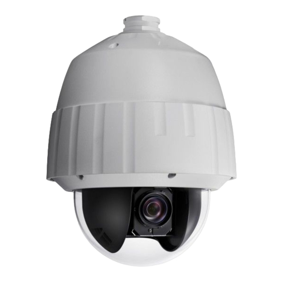
User Manual of HD-TVI Speed Dome Chapter 1 Overview 1.1 Description Integrated with the built-in pan/tilt unit, the E series speed dome features highly sensitive response and reliable performance. The speed dome can be adopted in various surveillance fields with its full-integral functions and features, such as corridor, large venue, meeting room, station, neighborhoods, etc. - Page 8 User Manual of HD-TVI Speed Dome In manual tracking mode, when a target object goes directly beneath the dome, the video will automatically flips 180 degrees in horizontal direction to maintain continuity of tracking. This function can also be realized by auto mirror image depending on different camera models. ...
- Page 9 User Manual of HD-TVI Speed Dome are in auto status during the pattern is being memorized. Power Off Memory The dome supports the power off memory capability with the predefined resume time. It allows the dome to resume its previous position after power is restored. ...
-
Page 10: Chapter 2 Getting Started
User Manual of HD-TVI Speed Dome Chapter 2 Getting Started 2.1 Power-up Action After the speed dome is power-on, it will perform a series of self-test actions. It runs the pan checking firstly, then the tilt checking and the camera checking at last. After the power-up actions, the system information will be displayed for 2 minutes on the live view screen as shown below. -
Page 11: System-Defined Presets
User Manual of HD-TVI Speed Dome etc. In this manual, accessing the speed dome via the web browser will be taken as an example. Panning and tilting: Click the direction buttons to control the pan and tilt movement of the speed dome. Zooming: Click the ZOOM+ and ZOOM- buttons to control the zooming. - Page 12 User Manual of HD-TVI Speed Dome Zoom Ratio: Identifies the amount of magnification. The format is ZXXX. XXX is the zoom amount. PT Angle: Displays panning and tilting direction, with the format of NEXXX/TXXX. The NE followed with XXX indicates the degrees in north east direction, while the T followed with XXX indicates the degrees in tilt position.
-
Page 13: Chapter 3 Menu Operation
User Manual of HD-TVI Speed Dome Chapter 3 Menu Operation The operation interface of the different speed domes may differ. Please refer to the actual operation interface. You can click the left and right direction buttons in the PTZ control panel via the web browser of the DVR to enter the next page or return to the previous page of the submenu if more than one page is available. -
Page 14: Configuring System Information
User Manual of HD-TVI Speed Dome Steps: 1. Connect the video and RS-485 cables of speed dome to a DVR. 2. Visit the DVR via the web browser. 3. View the live video of the speed dome. 4. For PELCO-P/D and other private PTZ protocols, call preset 95 from the preset list in the PTZ control panel of the DVR. -
Page 15: Configuring System Parameters
User Manual of HD-TVI Speed Dome MAIN MENUS > SYSTEM INFO SYS INFO SYS INFO CAM VERSION X.XX XX-XXXXX-X PARAM DATE X XX XX ADDRESS TEMPERATURE COM FORMAT 2400,8,1 PROTOCOL SELF ADAPTIVE VERSION 1.00 HARDVERSION 1.00 BUILD DATE 13 04 01 BACK EXIT BACK... - Page 16 User Manual of HD-TVI Speed Dome If the SET SOFT ADDR is set as OFF, the hard address set by the DIP switch is the valid address of the speed dome. Before you set the soft address of the speed dome, you need to confirm that it is within the control range of the control device (e.g.
- Page 17 User Manual of HD-TVI Speed Dome Angle Zero Configuration Purpose: You can define the angle zero of the speed dome on the ANGLE ZERO submenu. Steps: (1) Move the cursor to ANGLE ZERO using the direction buttons and click IRIS+ to enter. (2) Click the left/right/up/down direction buttons to adjust the monitor angle of the speed dome.
- Page 18 User Manual of HD-TVI Speed Dome Fan Parameter Configuration You can set the FAN CONTROL as TEMP (controlled by the temperature), ON or OFF. EIS (Electronic Image Stabilization) Configuration You can set the EIS FUNCTION as ON or OFF; and set the EIS LEVEL as 0-3. The selectable EIS level varies according to the different camera models.
-
Page 19: Configuring Image Parameters
User Manual of HD-TVI Speed Dome 3.3 Configuring Image Parameters 3.3.1 Configuring Camera Parameters Purpose: You can set the camera parameters including focus, shutter speed, iris, etc. Enter the camera parameters settings menu: MAIN MENUS > DOME SETTINGS >CAMERA SETTINGS CAMERA CAMERA FOCUS... - Page 20 User Manual of HD-TVI Speed Dome longer when the target is at a distance, to avoid the speed dome focusing on the objects close to it; or configure the focus limit shorter when the target is near the speed dome, and avoid it focuses on the objects father.
- Page 21 User Manual of HD-TVI Speed Dome cut filter mode to DAY mode and call preset 40 to set it as NIGHT mode. The DAY/NIGHT value cannot be configured unless the IR light is turned off. D/N sensitivity. The D/N sensitivity is the light level for auto D/N mode switch. As a threshold, IR cut filter switches between DAY and NIGHT when the light condition reaches the user-defined D/N level.
- Page 22 User Manual of HD-TVI Speed Dome Set the Gain 1. Gain value. The value of gain indicates the amplification degree of the original image signal. You can set the value from 0 to 15. 2. Gain limit. The higher gain value you set, the more noises will appear in the image. You can set the maximum user configurable gain value from 0 to 15 to limit the gain range and control the noises in the image.
- Page 23 User Manual of HD-TVI Speed Dome ATW: In auto-tracking mode, white balance is continuously being adjusted in real-time according to the color temperature of the scene illumination. HAUTO: Selecting this mode, the viewed image retains color balance automatically according to the current color temperature.
-
Page 24: Configuring Privacy Mask
User Manual of HD-TVI Speed Dome The contrast function is supported by certain camera model series. HLC Set the value of HLC to brighten the darker area and weaken the highlight area of the image. The greater the value is, the stronger the effect will be. The HLC function is supported by certain camera model series. -
Page 25: Configuring Output Standard
User Manual of HD-TVI Speed Dome Steps: (1) Move the cursor to SET BLANK and click IRIS+ button to enter the editing mode as shown in the following figure. You can see a privacy mask on the live window. ADJUST MASK POS FOCUS SHIFT STATUS IRIS + SAVE IRIS - CANCEL... -
Page 26: Configuring Ir Parameters
User Manual of HD-TVI Speed Dome 3. Click the up and down direction buttons to select a desired video standard. 4. Click IRIS+ again to confirm and exit the editing mode. 3.3.4 Configuring IR Parameters The IR parameter settings are supported by IR speed domes only. Purpose: You can configure the IR parameters including the IR sensitivity, n/m LED current, reference height, reference zoom, and LED control, fan control, switch delay, heat control, and IR correction, etc. -
Page 27: Configuring Ptz Control Parameters
User Manual of HD-TVI Speed Dome The SWITCH DELAY(S) refers to the delay time between the switch of far-distance IR LED and N/M-distance IR LED. 3.4 Configuring PTZ Control Parameters Purpose: You can configure panning, tilting and zooming movements, and configure PTZ control functions including presets, patrols, patterns, etc. - Page 28 User Manual of HD-TVI Speed Dome Park time and actions Purpose: This feature allows the speed dome to start a predefined action (park action: scan, preset, pattern, etc.) automatically after a period of inactivity (park time). You can set PARK TIME from 5 to 720 seconds and set the park action (PARK ACT) as preset 1-8, pattern 1-5, patrol 1-10, pan scan, tilt scan, panoramic scan, day mode, night mode or none.
-
Page 29: Configuring Presets
User Manual of HD-TVI Speed Dome The new limit will overwrite the existed ones by default. 5. You can clear the defined limits. Click IRIS+ to enter CLEAR LIMITS and click IRIS+ again to clear the stops. Elevation set You can set the SET ELEVATION as ON to increase the elevation angle range of the speed dome or set it as OFF to disable the function. -
Page 30: Configuring Patrols
User Manual of HD-TVI Speed Dome Move the cursor to PRESET PTZ and click IRIS+ to edit the preset position. Use the direction buttons to move the speed dome to find the desired scene/position, and then press IRIS+ to confirm the settings and return to the previous menu, or press IRIS- to cancel. The preset position settings will be restricted by the limits if they are defined. -
Page 31: Configuring Patterns
User Manual of HD-TVI Speed Dome NUM PST DWELL SPEED IRIS+ OK IRIS- CANCEL Figure 3-14 Edit the Patrol (2) Click up/down direction buttons to choose the number and locate the preset to be edited. (3) Click left/right direction buttons to position the cursor to the column of PRESET, DWELL and SPEED. - Page 32 User Manual of HD-TVI Speed Dome recalled by a command or automatically performed by a configured function (alarm, park, timing task, and power-up). Steps: 1. Move the cursor to enter the PATTERNS submenu: MAIN MENU > DOME SETTINGS > PATTERNS PATTERNS PATTERN NO.
-
Page 33: Configuring Timing Tasks
User Manual of HD-TVI Speed Dome patterns. When it reaches 0, no more patterns can be configured. You can also see the remaining memory shown under PATTERNS menu as REMAINING. The pan/tilt movements and the lens operations cannot be memorized simultaneously. 4. - Page 34 User Manual of HD-TVI Speed Dome Up to 8 timing tasks can be configured. 3. Set the task status. (1) Move the cursor to ENABLE TASK and click IRIS+ to enter edit mode. (2) Click the up/down direction buttons to set the task status to ON. (3) Click IRIS+ again to confirm the settings and exit edit mode of this column.
-
Page 35: Configuring Zone
User Manual of HD-TVI Speed Dome 3.4.6 Configuring Zone Purpose: A zone is a panning and tilting area defined by the left/right limits. You can configure the zones on ZONES submenu. You can define a zone when the targeted surveillance scene is limited. Steps: 1. -
Page 36: Configuring And Handling Alarms
User Manual of HD-TVI Speed Dome 3.5 Configuring and Handling Alarms The alarm related function is not supported by the 7-inch IR speed dome. 3.5.1 Configuring Alarm Input and Linkage Actions Purpose: This section explains how to configure the speed dome to respond to alarm events with alarm linked actions, such as calling presets, patrols, patterns, scanning, etc. -
Page 37: Configuring Alarm Parameters
User Manual of HD-TVI Speed Dome 5. Configure the alarm linkage action. You can specify the linked action when an alarm occurs. (1) Move the cursor to LINKAGE and click the IRIS+ to enter edit mode. (2) Click the up and down direction buttons to choose the desired linkage action. You can set the alarm action as preset from 1 to 8, pattern from 1 to 5, patrol from 1 to 10, panning scan, tilting scan, panoramic scan, day mode, night mode or none. -
Page 38: Configuring Alarm Output
User Manual of HD-TVI Speed Dome 3.5.3 Configuring Alarm Output Purpose: An alarm output is a configurable alarm output interface on the speed dome back box which can connect and trigger another alarm device to operate. Steps: 1. Enter the alarm output configuration submenu: MAIN MENUS >... -
Page 39: Others
User Manual of HD-TVI Speed Dome 3.6 Others 3.6.1 Restoring Default Dome Settings Purpose: You can reset all dome settings to factory default parameters as shown in the table below. Dome settings are mainly of PTZ parameters and alarm parameters, and also include some system settings, e.g. -
Page 40: Appendix
User Manual of HD-TVI Speed Dome Appendix Appendix 1 Lightning & Surge Protection This product adopts TVS plate lightning protection technology to avoid damage caused by pulse signal that is below 3000W, like instantaneous lighting stroke, surging, etc. According to the actual outdoor situation, necessary protection measures must be taken, besides ensuring the electrical safety. -
Page 41: Appendix 2 Rs485 Bus Connection
User Manual of HD-TVI Speed Dome Appendix 2 RS485 Bus Connection General Property of RS485 Bus According to RS485 industry bus standard, RS485 is a half-duplex communication bus which has 120Ω characteristic impendence, the maximum load ability is 32 payloads (including controller device and controlled device). - Page 42 User Manual of HD-TVI Speed Dome Controller Figure A-4 Star Shape Connection For such case, the best way is adding a RS485 distributor. This product can effectively change the star-shape connection to which satisfies the requirement of RS485 industry standard, in order to avoid those problems and improve the communication reliability.
- Page 43 User Manual of HD-TVI Speed Dome Problem Possible Reasons To Solve the Problem dome can tightly. 2. RS485+ or RS485-wire is 2. Change a RS485 wire. controlled broken. but not 3. The speed dome is too far away 3. Add a terminal resistor. smoothly.
-
Page 44: Appendix 3 24Vac Wire Gauge & Transmission Distance
User Manual of HD-TVI Speed Dome Appendix 3 24VAC Wire Gauge & Transmission Distance The following table describes the recommended Max. distance adopted for the certain wire gauge when the loss rate of 24VAC voltage is less than 10%. For the AC driven device, the maximum voltage loss rate is 10% allowable. -
Page 45: Appendix 4 Wire Gauge Standards
User Manual of HD-TVI Speed Dome Appendix 4 Wire Gauge Standards American Cross-sectional Bare Wire British Wire Wire Gauge Area of Bare Gauge(mm) Gauge SWG Wire(mm 0.750 0.4417 0.800 0.5027 0.900 0.6362 1.000 0.7854 1.250 1.2266 1.500 1.7663 2.000 3.1420 2.500 4.9080 3.000...
Need help?
Do you have a question about the Winic RedLine CT-AP313-OD and is the answer not in the manual?
Questions and answers