Table of Contents
Advertisement
Quick Links
Littfinski DatenTechnik (LDT)
•
Bühler electronic GmbH
DigitalBooster DB-4
The DigitalBooster DB-4 is a short-circuit protected
Power-Amplifier (Booster) for digital Model Railway
Layouts from the Digital-Professional-Series!
The DB-4 amplifies the digital formats of Märklin-
>> finished module in a case <<
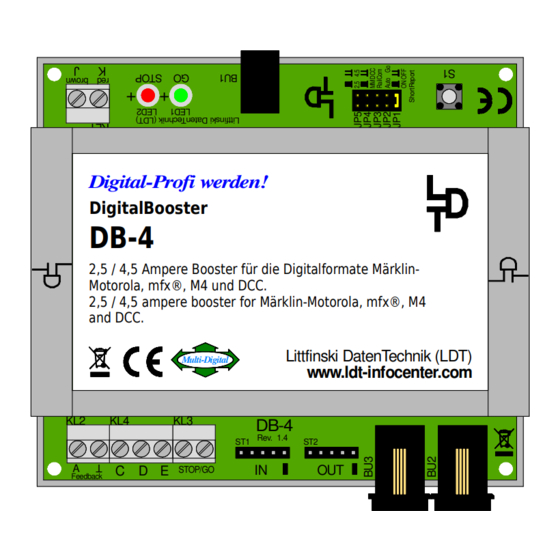
Digital-Profi werden!
DigitalBooster
DB-4
2,5 / 4,5 Ampere Booster für die Digitalformate Märklin-
Motorola, mfx®, M4 und DCC.
2,5 / 4,5 ampere booster for Märklin-Motorola, mfx®, M4
and DCC.
Multi-Digital
KL2
KL4
KL3
ST1
A
C D E
STOP/GO
Feedback
This product is not a toy! Not suitable for children under 14 years. Improper use will imply danger or injuries due to
sharp edges and tips! Please store this instruction carefully.
Multi-Digital
•
Ulmenstraße 43
15370 Fredersdorf / Germany
Manual
Motorola, mfx
DB-4-G
Part-No.:
Littfinski DatenTechnik (LDT)
www.ldt-infocenter.com
DB-4
Rev. 1.4
ST2
IN
OUT
•
Tel.: +49 (0) 33439 / 867-0
®
, M4 and DCC.
080073
The DigitalBooster DB-4 provides a
maximum digital current of 2.5 or 4.5
Ampere and amplifies the digital
formats of Märklin-Motorola, mfx
and DCC.
The DB-4 can operate with several
digital command stations by using the
5-poles booster bus, the CDE booster
bus or the Roco-booster bus.
The DigitalBooster DB-4 receives the
power supply not from a classical
model railway transformer but from
the switched mode mains power
supply DB-4 PowerSupply. On this
unit is the stabilized digital track
voltage adjustable between 15 and 24
Volt, suitable for all track gauges.
®
, M4
Advertisement
Table of Contents

Related Manuals for Littfinski Daten Technik DigitalBooster DB-4

Summary of Contents for Littfinski Daten Technik DigitalBooster DB-4
- Page 1 Ulmenstraße 43 15370 Fredersdorf / Germany Tel.: +49 (0) 33439 / 867-0 Manual DigitalBooster DB-4 The DigitalBooster DB-4 is a short-circuit protected Power-Amplifier (Booster) for digital Model Railway Layouts from the Digital-Professional-Series! The DB-4 amplifies the digital formats of Märklin- ®...
-
Page 2: Table Of Contents
DigitalBooster DB-4 – Manual Content: Page Preface / Safety Instruction DB-4 connection to the digital command station or to other boosters 2.1. DB-4 connection via the 5-poles Boosterbus 2.2. DB-4 connection via the CDE-Booster bus 2.3. DB-4 connection via the Roco-Booster bus... -
Page 3: Preface / Safety Instruction
• Many illustrations at this manual are identified with a file name (e.g. page_937). You can find those files on our Web-Site at the section “Sample Connections” of the DigitalBooster DB-4. You can download the files as PDF-File and make a colored print at the DIN A4 format. -
Page 4: Connection To The Digital Command Station Or To Other
Viessmann Commander 2.1. DB-4 connection via the 5-poles Boosterbus: The DigitalBooster DB-4 can be connected by use of the 5-poles boosterbus cable (order code: Kabel Booster 1m, Part-No.: 000123), to one of the command stations as per above table or to other boosters (e.g. DB-4, DB-2, 6015, 6017, Power 2, Power 3). -
Page 5: Connection Via The Cde-Boosterbus
Bestellbezeichnung / Order code: Kabel Booster 1m page_1117 DigitalBooster DB-4 connection to the command station and between each other via the 5-poles boosterbus. 2.2. DB-4 connection via the CDE-Boosterbus: If your Command Station contains a CDE-Boosterbus the connection to the DigitalBoosters DB-4 can be realized with three cables. - Page 6 C D E STOP/GO Feedback braun digital brown Keyboard 1: 1/2 Grün Grün V200 021 mobile station STOP STOP SHIFT page_1358 Connection of the DigitalBooster DB-4 via the connection C and D with the Mobile Station 2 and the track-box.
-
Page 7: Connection Via The Roco-Boosterbus
3. DB-4 connection to the Switched Mode Mains Power Supply DB-4- PowerSupply: The DigitalBooster DB-4 shall not get the power supply over the socket BU1 from a classical model railway transformer but from the Switched Mode Mains Power Supply DB-4-PowerSupply. -
Page 8: Connection To An Own Track Section
4. DB-4 connection to an Own Track Section: The DigitalBooster DB-4 is a power amplifier for your digital model railway layout. The digital current of the DigitalBooster DB-4 is available at the clamp KL1 next to the two light emitting diodes. - Page 9 DigitalBooster DB-4 – Manual If the manufacturer of the digital command station does not permit a common layout ground (“brown”) it is required additionally to isolate the rails at the cross over joints. If the manufacturer of the digital command station stipulates mandatory the installation of a rocker switch at the cross sections of the center conductor this switch has to be installed.
- Page 10 DigitalBooster DB-4 – Manual 4.2. 2-Conductor Track System: If the manufacturer of your digital command station permits a common layout ground (“brown” or “J”) one rail of the 2-conductor track has to be isolated at the cross over joints from one to the next booster electrical circuit.
- Page 11 DigitalBooster DB-4 – Manual 5. Booster in Operation: All jumpers of the DB-4 are set ex-factory. The DigitalBooster DB-4 can be used immediately at the supplied condition. The factory setting is recommended for the first implementation of the unit. For selecting different operation modes after the first implementation please attend to the chapter “Adjusting Operation Modes with Jumpers”.
- Page 12 6.4. Short Circuit Report to the Command Station (Short Report): If the Jumper J1 "Short Report" has been set the DigitalBooster DB-4 will report a short circuit within the connected track section via the used booster bus to the digital command station.
- Page 13 6.5. Automatic Switch-On (Auto Go): With the jumper J2 “Auto Go” is it possible to adjust the DigitalBooster DB-4 that the unit perform a continuous check every 5 seconds if the short-circuit is still present.
- Page 14 / green / + 7.1. Common Address Section: If there will be a common four-fold address block programmed for the WatchDog- and the On-/Off switch function the DigitalBooster DB-4 will occupy 4 accessory- or turnout addresses. WatchDog On-/Off sw. Funktion...
- Page 15 WatchDog 7.3. Address Section Programming: 1. Switch-on your digital layout incl. DigitalBooster DB-4 (the green LED of the DB-4 will glow). Depress 1x short the key S1 next to the jumpers of the DB-4. Now the green LED flashes. This indicates that the DB-4 is in the programming mode for the address-section of the On-/Off switch-function.
- Page 16 WatchDog- Function. If the DigitalBooster DB-4 understands the address the DB-4 will confirm the assignment by flashing the red LED a little faster. Following the red LED will flash slower again.
- Page 17 The DigitalBooster DB-4 can be switched On and Off via an accessory address (turnout command). Address programming explained in chapter 6. The DigitalBooster DB-4 can be switched Off via the basic address + 2 “round” of the address block programmed for the On/Off-switch function. The DigitalBooster DB-4 can be switched On via the basic address + 2 “straight”.
- Page 18 The switching-on of all boosters can be done only with the Go-Key of the digital command station. If the jumper J1 “Short Report” has been removed is it possible to switch the DigitalBooster DB-4 which is connected to the external Stop/Go keys individually On and Off. Fahren und Schalten...
- Page 19 DigitalBooster DB-4 – Manual 11. Feedback Report for Booster-Management: The DigitalBooster DB-4 contains a Feedback Output for the information to the model railway software if the tracks receive digital current from the DB-4 or if this has been temporarily interrupted caused e.g. by a short circuit or by an emergency shutdown.
- Page 20 DigitalBooster DB-4 – Manual 12. Assembly Plan of the Basic PC-board: Made in Europe by Littfinski DatenTechnik (LDT) Bühler electronic GmbH Ulmenstraße 43 15370 Fredersdorf / Germany Phone: +49 (0) 33439 / 867-0 Internet: www.ldt-infocenter.com Subject to technical changes and errors. © 02/2022 by LDT Märklin and Motorola are registered trademarks.
Need help?
Do you have a question about the DigitalBooster DB-4 and is the answer not in the manual?
Questions and answers