
Subscribe to Our Youtube Channel
Related Manuals for HTW VAX HTW-ATS-O-500VAX


Summary of Contents for HTW VAX HTW-ATS-O-500VAX
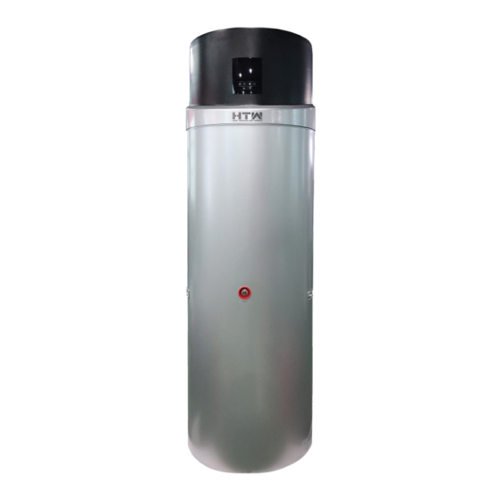
- Page 1 OWNER’S AND INSTALLATION MANUAL SANITARY WATER HEAT PUMP VAX 500 lit. HTW-ATS-O-500VAX Thanks for choosing our product. Please, read carefully this manual before using the product...
-
Page 2: Table Of Contents
ENVIRONMENTAL INFORMATION........................26 DISPOSAL REQUIREMENTS..........................27 WIRING DIAGRAM..............................28 TECHNICAL SPECIFICATION..........................30 HTW-ATS-O-***VAX............................30 TEMPERATURE SENSOR R-T CONVERSION TABLE...................32 READ THIS MANUAL CAREFULLY BEFORE STARTING UP THE UNIT. DO NOT THROW IT AWAY.KEEP IT IN YOUR FILES FOR FUTURE REFERENCE. BEFORE OPERATING THE UNIT, MAKE SURE THE INSTALLATION HAS BEEN CARRIED OUT CORRECTLY BY A PROFESSIONAL DEALER. -
Page 3: Introduction
INTRODUCTION This manual This manual includes the necessary information about the unit. Please read this manual carefully before you use and maintain the unit. The unit The hot water heat pump is one of the most economical systems to heat the water for family domestic use. -
Page 4: Safety Instructions
Multiple Functions The special design of the air inlet and outlet makes the unit suitable for various ways of connections. With different ways of installation, the unit can work as just a heat pump but also as a fresh air blower, a dehumidifier, or an energy recovery device. - Page 5 Be sure to use the provided or specified parts for the installation work. The use of defective parts could cause an injury due to possible fire, electric shocks, the unit falling etc. Perform the installation securely and please refer to the installation instructions. Incorrect installation could cause an injury due to possible fire, electric shocks, the unit falling, leakage of water etc.
-
Page 6: Caution
Caution Do not install the unit in a place where there is a chance of flammable gas leaks. If there is a gas leak and gas accumulates in the area surrounding the unit, it could cause an explosion. Perform the drainage/piping work according to the installation instruction. If there is a defect in the drainage/piping work, water could leak from the unit and household goods could get wet and be damaged. -
Page 7: Items Inside Product Box
ITEMS INSIDE PRODUCT BOX Before starting the installation, please make sure that all parts are found inside the box. The Unit Box Item Image Quantity Domestic hot water heat pump Operation and Installation Manual... -
Page 8: Overview Of The Unit
OVERVIEW OF THE UNIT Parts and descriptions... -
Page 9: Dimensions
Dimensions Model: HTW-ATS-O-***VAX 300L 300LS 500L 500LS Φ640 Φ640 Φ700 Φ700 Φ177 Φ177 Φ177 Φ177 1280 1280 1680 1680 1040 1040 1420 1420 1845 1845 2250 2250 1140 1140 1520 1520 32.5 32.5 32.5 32.5 1230 1230 1633 1633 Remark: 1) The extra heat source is optional. -
Page 10: How To Replace The Magnesium Stick
creation of fur around the inside tank and to protect the tank, and other components. It can help to extend the life-span of the tank. Check the magnesium stick every half year and change it if it has been used out!Note: replace by professional. -
Page 11: Installation
INSTALLATION Asked your supplier to install the unit. Incomplete installation performed by yourself may result in a water leakage, electric shock, or fire. Indoor installation is highly recommended. It is not allow to install the unit at outdoor or rain achieving place. -
Page 12: Required Service Space
Required service space Below you will find the minimum space required to be able to complete service and maintenance tasks on the units. Note: If air inlet and/or outlet pipes are connected, portion airflow and capacity in heat pump unit will lose. -
Page 13: Installation Overview
Installation overview Note: Solar heat exchange coil is optional. ATTENTION: The one-way safety valve must be installed. If not, it could cause damage to the unit, or even hurt people. The set point of this safety valve is 0.7 MPa. For the installation place please refer to the pipeline connection sketch. - Page 14 The water may drip from the discharge pipe of the one-way safety valve and that this pipe must be left open to the atmosphere. The one-way safety valve is to be operated regularly to remove lime deposits and to verify that it is not blocked.
-
Page 15: Installation Positions
Installation positions (1) Waste heat can be useful heat Units can be installed near the kitchen, in the boiler-room or the garage, basically in every room which has a large number of waste-heat so that the unit has the higher energy efficiency even with very low outside temperatures during the winter. -
Page 16: Water Loop Connection
Water loop connection Please pay attention to the below points when connecting the water loop pipe: 1. Try to reduce the water loop resistance 2. Make sure there is nothing in the pipe and the water loop is smooth, check the pipe carefully to see if there is any leak, and then pack the pipe with the insulation. -
Page 17: Wire Connection
Wire connection • The specification of the power supply wire is 3*1.5 mm². • Fuse specification is T 3.15A 250V • There must be a switch when connecting the unit to the power system. The current of the switch is 16A. •... -
Page 18: Operation The Unit
OPERATION THE UNIT User interface and operation Electrical heater Set button ‘ON’/’OFF’ button Unit ‘ON’/’OFF’ button Clock/Timer setting button UP adjust button DOWN adjust button Operations 1. Power ‘ON’ When turning ‘ON’ the power, whole icons are displayed on the controller screen for 3 seconds. After checking if everything is ok, the unit enters into the standby mode. - Page 19 buttons These are the multi-purpose buttons. They are used for the temp setting, parameter setting, parameter checking, clock adjustment and adjustment of the timer. During running status, press button to adjust the setting temperature directly. Press these buttons when the unit is on clock setting status, the hour(s) and the minute(s) of the clock time can be adjusted.
- Page 20 NOTE: 1) The timer ‘ON’ and timer ‘OFF’ functions can be set at the same time. 2) The timer settings are repeating. 3) The timer settings are still valid after a sudden power cut. 6. button 1) When the heat pump is ON, press this button to turn ‘ON’ the electrical heater. The heater icon will be showed, and the electrical heater will work according to the control program (parameter 3).
-
Page 21: Lcd Icons
LED icons 1. Hot water available The icon indicates that the domestic hot water temperature reaches the set point. The hot water is available for use. Heat pump is standby. 2. Fan ventilation The icon indicates that the fan ventilation function is enabled. When the unit is on, press the button and hold it for 5 seconds the fan ventilation function can be enabled or disabled. - Page 22 8. Right temperature display The display shows the current downside temperature of the water tank. When checking or adjusting the parameters, this section will display the related parameter value. In case any malfunction occurs, this section will display the related error code. 9.
-
Page 23: Parameter Checking And Adustment
PARAMETER CHECKING AND ADUSTMENT Parameter list Some system parameters can be checked and adjusted by the controller. Below is the parameter list: Parameter Description Range Default Remarks Tank water setting temp. 10 ~ 70°C 50°C Adjustable Water temperature gap 2 ~ 15°C 5°C Adjustable to restart... -
Page 24: Malfunctioning Of The Unit And Error Codes
malfunction Actual testing value. Error code P4 Return gas temp. sensor -9 ~ 99°C will be shown in case of a detect range malfunction Actual testing value. Error code P5 Ambient temp. sensor -9 ~ 99°C will be shown in case of a detect range malfunction Electronic expansion valve step... - Page 25 temp. sensor ● circuit connection failure (5 flashes 1 2) The sensor short 2) Replace the sensor dark) circuit 3) change the PCB board 3) PCB board failure 1) The sensor open 1) Check the sensor ☆ ☆ ☆ ☆ ☆ circuit Solar temp.
-
Page 26: Maintenance
1) If the tank water temp is 1) Too high tank water over 85C, the switch will temp ☆☆☆☆☆ Over heat open and the unit will stop for switch ☆☆☆● protection protection. After the water (8 flashes 1 damaged (HTP Switch) comes to normal temp, dark) 3) PCB board failure... -
Page 27: Troubleshooting
Check the power supply and the electrical system, make sure the electrical components are good, and the wiring is well. If there is a damaged part or a strange smell, please replace it in time. If the heat pump is not used for a long time, please drain out all the water from the unit and seal ... -
Page 28: Disposal Requirements
DISPOSAL REQUIREMENTS Dismantling of the unit, treatment of the refrigerant, of oil and of other parts must be done in accordance with relevant local and national legislation. Your product is marked with this symbol. This means that electrical and electronic products shall not be mixed with unsorted household waste. -
Page 29: Wiring Diagram
WIRING DIAGRAM Please refer to the wiring diagram on the electric box. HTW-ATS-O-300VAX(S) - Page 30 HTW-ATS-O-500VAX (S)
-
Page 31: Technical Specification
TECHNICAL SPECIFICATION TECHNICAL DATA 300L 300LS 500L 500LS Power supply V/Ph/Hz 220-240/1/50 Water tank Volume Max power input 700+1600 (e-heater) 1420+1600 (e-heater) Max current 3.2 +6.8 (e-heater) 6.2 +6.8 (e-heater) Max.outlet water °C temperature range(without using E-heater) Max. water temperature °C Min. - Page 32 Net Dimensions φ640x1845 φ640x1845 Φ700x2250 Φ700x2250 Packing Dimensions 695x695x1965 695x695x1965 750x750x2355 750x750x2355 Net Weight Gross Weight Noise level dB (A) NOTES: * During disinfection, the max water temp could be up to 70°C by electrical heater...
-
Page 33: Temperature Sensor R-T Conversion Table
TEMPERATURE SENSOR R-T CONVERSION TABLE R25= 5.0KΩ±1.0% B25-50 = 3470K±1.0% Rmax/ Rmin /KΩ KΩ Rmax/ ℃ ℃ Rmin /KΩ KΩ Rmax/ KΩ Rmin KΩ ℃ KΩ KΩ /KΩ 36.195 37.303 38.441 5.779 5.847 5.914 1.343 1.374 1.406 34.402 35.437 36.499 5.558 5.62 5.683... - Page 34 TEMPERATURE SENSOR R-T CONVERSION TABLE Only use for the solar temp sensor B25/50 = 3950K±1.0% R25=50KΩ±1.0% R(cent) R(cent) R(cent) R(cent) ℃ ℃ ℃ ℃ 466.6 78.38 17.93 5.227 441.1 74.85 17.26 5.061 417.2 71.5 16.61 4.902 394.7 68.32 15.99 4.748 373.5 65.29 15.4...
- Page 35 C./ Industria, 13 Polígono Industrial El Pedregar 08160 Montmeló Barcelona (Spain) Phone: 93 390 42 20 Fax: 93 390 42 05 info@htwspain.com...
Need help?
Do you have a question about the VAX HTW-ATS-O-500VAX and is the answer not in the manual?
Questions and answers