Advertisement
Quick Links
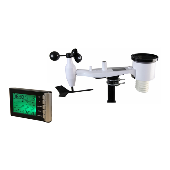
Wireless Weather Station
Model: PSG04174
Safety
Do not expose the main unit to rain or moisture
Use only recommended batteries
Remove the batteries if the weather station is not to be used for a
long time. Old batteries can begin to leak and damage the product.
Remember to insert the batteries according to the markings in the
battery compartment. The wrong polarity (+/-) can damage the
weather station.
Damage that has occurred by careless handling is not covered by
the warranty.
Production Description.
Display of indoor and outdoor temperature, wind speed, wind
direction, humidity, rainfall amounts, time and date
Alarm function for certain weather conditions as well as records of
1
Advertisement

Related Manuals for PRO SIGNAL PSG04174


Summary of Contents for PRO SIGNAL PSG04174
- Page 1 Wireless Weather Station Model: PSG04174 Safety Do not expose the main unit to rain or moisture Use only recommended batteries Remove the batteries if the weather station is not to be used for a long time. Old batteries can begin to leak and damage the product.
-
Page 2: Lcd Display
all minimum and maximum values along with time and date of their recordings Radio control time and date (DCF/WWVB/MSF version optional but only one Save the data when batteries is changed Operates on 5x LR6/AA alkaline batteries (not included) Contents Main unit (Display unit) Outdoor unit LCD Display... - Page 3 1. Time alarm on icon 16. Rainfall unit 2. DST icon (only available on 17. Outdoor temperature high WWVB version) alarm and low alarm 3. RCC tower icon for time reception 18. Outdoor temperature 4. Date of the week/time zone 19.
- Page 4 Set up Guide Figure 1 9 10 Figure 2 1. Wind Speed Sensor 2. Wind Vane 3. Thermo-hygro sensor 4. Rain collector 5. Bubble level 6. Solar panel 7. Antenna 8. U-Bolt 9. Battery compartment 10. Reset button 11. LED Indicator: lights for 4 seconds when the unit powers up. Then the LED will flash once every 48 seconds (the sensor transmission update period).
- Page 5 1. Install U-bolts and metal plate Installation of the U-bolts, which are used to mount the sensor package on a pole, requires installation of an included metal plate to receive the U-bolt ends. The metal plate, visible in Figure 3 has four holes through which the ends of the two U-Bolts will fit.
- Page 6 cups installed to install these bolts is more difficult and more likely to lead to damage. 2. Install wind speed cups Push the wind speed cup assembly onto the shaft on the top side of the sensor package, as shown in Figure 5 on the left side. Tighten the set screw, with a Philips screwdriver (size PH0), as shown on the right side.
- Page 7 Figure 6: Wind vane installation diagram 4. Install Batteries Open the battery compartment with a screwdriver and insert 2 AA batteries in the battery compartment. The LED indicator on the back of the sensor package will turn on for four seconds and then flash once every 48 seconds indicating sensor data transmission (the sensor transmission update period).
- Page 8 Note: If LED does not light up or is on permanently, make sure the battery is inserted the correct way and inserted fully, starting over if necessary. Do not install the batteries with incorrect polarity as it may permanently damage the outdoor sensor. Note: We recommend Lithium batteries for cold weather climates, but alkaline batteries are sufficient for most climates.
- Page 9 Note Beside the antenna, there is an arrow icon with an ident labelled ”WEST” (Figure 9) representing the direction of west. The sensor body has to be adjusted so that the “WEST” indication is facing to real west direction for your location. A compass device is recommended to help adjust direction.
- Page 10 RESET button LED light Figure 10 7. Best Practices for Wireless Communication Note: To insure proper communication, mount the remote sensor(s) upright on a vertical surface, such as a wall. Do not lay the sensor flat. Wireless communication is susceptible to interference, distance, walls and metal barriers.
- Page 11 The following is a table of reception loss vs. the transmission medium. Each “wall” or obstruction decreases the transmission range by the factor shown below. Medium RF Signal Strength Reduction Glass (untreated) 5-15% Plastics 10-15% Wood 10-40% Brick 10-40% Concrete 40-80% Metal 90-100%...
-
Page 12: Program Mode
Note for RCC signal: The best condition for reception is at night, between midnight and 6:00am – when there is less atmospheric interference. Note: If a battery change on the transmitter alone is made, the receiver will be resynchronized to the transmitter again within the next 3 hours. If you want to shorten the receiving data time, the base station also has to re-install the battery so that it can have the new security code learnt right way, but the previous weather data and alarm value settings in... - Page 13 Quick Display Mode - While in normal display, Press the SET key to enter the Quick Display Mode as follow: Wind speed / Gust speed (press the + key or MIN/MAX key shifts the display between the wind speed and gust speed) 1 hour / 24 hour / week / month / total rainfall quantity (press the + key or MIN/MAX key shifts the display between the selectable rainfall quantities), while display the rainfall total quantity, pressing...
- Page 14 Calibration Mode Press the HISTORY key for 8 second while in normal mode to enter the Calibration Mode, and the wind factor digits will start flashing. You can skip over any setting by press the SET key. Press + key or MIN/MAX key to select the units or scrolls the value.
- Page 15 Temperature Calibration Temperature errors can occur when a sensor is placed too close to a heat source (such as a building structure, the ground and when placed in direct sunlight without proper shielding in hot weather environments). To calibrate temperature, we recommend a mercury or red spirit (fluid) thermometer.
- Page 16 may not be accurate. Place the tube type rain gauge directly next to the rain collector. Compare the totals on three storms. Based on this, develop an average for how far off the readings are. Do not compare rainfall readings to reading obtained from television, radio, newspapers, or neighbors’...
- Page 17 Remark: after the initial pressing of ALARM key, the display will be refreshed to show current high, low alarm values. Normal alarm value will be displayed only for those already activated, all other not activated values will be displayed with “- - -“or “- -“instead. -In the High Alarm Mode press the SET key to select the following alarm modes: Time alarm...
- Page 18 (if alarm is enabled, the speaker icon on the LCD will be turned on indicating the alarm function has been enabled). - Press the SET key to toggle through each alarm mode until it returns to the normal display mode. -Press HISTORY key or key idle 30 second at any time, the alarm mode will return to Normal Mode Canceling the Temperature Alarm While Sounding...
- Page 19 Wind speed maximum Gust speed maximum1Hour rain maximum 24 hour rain maximum Week rainfall maximum Month rainfall maximum Outdoor humidity maximum Outdoor temperature maximum Wind chill temperature maximum Dew point temperature maximum 10. Indoor humidity maximum 11. Indoor temperature maximum - In the minimum reading Mode, press the + key to display the following minimum values together with the time and date at which these values were recorded, if hold the SET key for 3s in the following individual...
-
Page 20: Specifications
Specifications Outdoor data Transmission distance in open field : 100m(300 feet) : 868Mhz Frequency : -40˚C—60˚C (-40 to +149℉℉) Temperature range : + / - 1 °C Accuracy : 0.1˚C Resolution : 10%~99% Measuring range rel. humidity : +/- 5% Accuracy : 0 –... - Page 21 Remark: Where outdoor temperature is lower than -20˚C, make sure proper type of batteries to be used to assure that the device can get enough power to maintain its function properly. Normal alkaline batteries is not allow to be used since when outdoor temperature is lower than -20 ˚C, the battery’s discharging capability is greatly reduced.
- Page 22 INFORMATION ON WASTE DISPOSAL FOR CONSUMERS OF ELECTRICAL & ELECTRONIC EQUIPMENT These symbols indicate that separate collection of Waste Electrical and Electronic Equipment (WEEE) or waste batteries is required. Do not dispose of these items with general household waste. Separate for the treatment, recovery and recycling of the materials used.
Need help?
Do you have a question about the PSG04174 and is the answer not in the manual?
Questions and answers