
Summary of Contents for TW Electronic Components LP444s
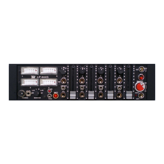
- Page 1 ELECTRONIC COMPONENTS LP444s USER MANUAL TW LP444s is a compact portable 4 in / 2 out and switchable 4 in / 4 out unit designed for four-track recorder or camera.
- Page 2 LEFT SIDE PANEL Balanced channel inputs – four electronically balanced circuits (transformer balanced is optional) in phase with one another. XLR connectors should be wired as pin1 ground, pin2 +phase signal and pin3 –phase signal. Microphone powering selector switches – The input sensitivity in position D is DYN 200 = 0.2 mV and no power.
- Page 3 FRONT PANEL 4 / 4 switch – The TW LP444s mixer works in stereo mode when this switch is turned down. Turned to 4 / 4 position, channel 1 Pan switched in L, channel 2 in R, the four inputs can be controlled independently by the channel faders to the four outputs.
- Page 4 EE / RTN12 switch – A two-position switch selects the direct outputs from the mixer or the return 1 and 2 as a signal source for the monitoring. Master – The fader sets the gain of both Left and Right legs and has +6 dB of gain in hand with the nominal 0 dB gain position marked.
- Page 5 RIGHT SIDE PANEL Balanced outputs – The four main outputs are via transformer balanced XLR connectors. Left and Right outputs are linked a Hirose 10pin multiway connector to facilitate rapid connection of outputs and monitor returns. The line level is set on 600 Ω at 0 dBu and +4 dBu for VU metered mixers. The Hirose 10pin connector is wired as follows: pin 1.
- Page 6 ADJUSTMENT POINTS Gain and modulometer adjustment – Connect an AC voltmeter to the Left balanced line output. Set channel 1 pan switch to L position, turn channel 1 fader fully clockwise, set Master at marked 0 dB and switch LFA off. Connect an audio generator 1 kHz 0 dBm attenuator –80 dB to Mic 1 Input and adjust TRIM to obtain 0 dBu (+4 dBu on VU metered mixers) at the Left balanced output.
- Page 8 SPECIFICATIONS Inputs Microphone: four balanced XLR female Sensitivity: –75 dBu Maximum input level: –20 dBu Microphone power: 48 V, 12 V, T (DIN AB) Line attenuation: adds 60 dB attenuation before the mic preamp. Signal to Noise ratio: > 65 dB, Equivalent Input Noise: –125 dBu Frequency response: 20 Hz - 20 kHz ±2 dB Harmonic distortion: less than 0.2 % Low-cut filter: 80 / 100 Hz / 14 dB octave...
Need help?
Do you have a question about the LP444s and is the answer not in the manual?
Questions and answers