Table of Contents
Advertisement
Quick Links
Advertisement
Table of Contents

Subscribe to Our Youtube Channel
Related Manuals for Icom IC-400BB


Summary of Contents for Icom IC-400BB
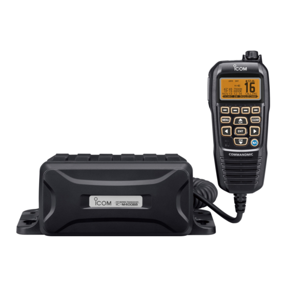
- Page 1 INSTRUCTION MANUAL VHF MARINE TRANSCEIVERS iM400BB iM400BBE This device complies with Part 15 of the FCC Rules. Opera- tion is subject to the condition that this device does not cause harmful interference. COMMANDMIC IV ™ (HM-195) may not be supplied, depending on the transceiver version.
-
Page 2: Important
• Force majeure, including, but not limited to, fires, earth- quakes, storms, floods, lightnings, or other natural disas- Icom, Icom Inc. and the Icom logo are registered trademarks of Icom Incor- porated (Japan) in Japan, the United States, the United Kingdom, Germany, ters, disturbances, riots, war, or radioactive contamination. -
Page 3: In Case Of Emergency
(Ch 70) are used. If higher gain antenna are required then please DISTRESS CALL PROCEDURE contact your Icom distributor for revised installation recom- 1. While lifting up the key cover, hold down [DISTRESS] mendations. for 3 seconds until you hear 3 short beeps and then one long beep. -
Page 4: Radio Operator Warning
RADIO OPERATOR WARNING FAILURE TO OBSERVE THESE LIMITS MAY ALLOW Icom requires the radio operator to meet the THOSE WITHIN THE MPE RADIUS TO EXPERIENCE RF FCC and IC Requirements for Radio Fre- RADIATION ABSORPTION WHICH EXCEEDS THE MAXI- quency Exposure. An omnidirectional antenna MUM PERMISSIBLE EXPOSURE (MPE) LIMIT. -
Page 5: Avertissement Pour Les Opérateurs Radio
AVERTISSEMENT POUR LES OPÉRATEURS RADIO Icom exige que l’opérateur radio se conforme LE NON-RESPECT DE CES LIMITES PEUT CAUSER, POUR LES aux exigences de la FCC et d’IC en matière PERSONNES SITUÉES DANS LE RAYON D’EXPOSITION MAXI- d’exposition aux radiofréquences. Une antenne MALE ADMISSIBLE, UNE ABSORPTION DE RAYONNEMENT omnidirectionnelle dont le gain ne dépasse pas 9... -
Page 6: Fcc Information
Operation of this equipment in a residential area is likely to been dropped. Contact your Icom distributor or your dealer for advice. cause harmful interference in which case the user will be re- quired to correct the interference at his own expense. -
Page 7: Precautions
PRECAUTIONS RWARNING! NEVER DO NOT connect the transceiver to an AC use harsh solvents such as benzine or alcohol to outlet. This may pose a fire hazard or result in an electric shock. clean the transceiver, as they will damage the transceiver’s surfaces. -
Page 8: Table Of Contents
TABLE OF CONTENTS IMPORTANT ................i 4 CONNECTIONS AND MAINTENANCE ....6–10 EXPLICIT DEFINITIONS ............i ■ Connections ..............6 IN CASE OF EMERGENCY ..........ii ■ Supplied accessories ...........8 INSTALLATION NOTE ............ii ■ Fuse replacement ............8 RADIO OPERATOR WARNING .......... iii ■... -
Page 9: Operating Rules
OPERATING RULES D Priorities (2) OPERATOR’S LICENSE A Restricted Radiotelephone Operator Permit is the license • Read all rules and regulations pertaining to call priorities, most often held by small vessel radio operators when a radio and keep an up-to-date copy handy. Safety and distress is not required for safety purposes. -
Page 10: Preparation
PREPARATION ■ MMSI code programming The 9 digit MMSI (Maritime Mobile Service Identity: DSC self r Repeat step e to enter all 9 digits. ID) code can be programmed at power ON. t After entering the 9 digit code, “FINISH” is automatically The code is programmed by using the HM-195. -
Page 11: Atis Code Programming
PREPARATION ■ ATIS code programming (For Dutch version and German version* transceivers) The 10 digit ATIS (Automatic Transmitter Identification Sys- r Repeat step e to enter all 10 digits. tem) code can be programmed at power ON. t After entering the 10 digit code, “FINISH” is automatically The code is programmed by using the HM-195. -
Page 12: Ais Transponder
AIS TRANSPONDER ■ Making an Individual call using an AIS transponder When the optional MA-500TR/MA-510TR CLASS B AIS TRANSPON- is connected to your transceiver, an individual DSC call can be transmitted to a selected AIS target, without needing to enter the target’s MMSI code. - Page 13 AIS TRANSPONDER r After making the individual DSC call, the transponder will ‘Able to comply’ is received display “DSC Transmission COMPLETED.” • Push [CLEAR] to return to the screen displayed before you en- tered the voice channel selection screen in step w. •...
-
Page 14: Connections And Maintenance
CONNECTIONS AND MAINTENANCE ■ Connections • The figure shows the IC-M400BBE. Green: Listener B (Data-L) Connects to an NMEA Out Negative line of a GPS receiver for position data. • A NMEA0183 ver. 2.0 or 3.01 RMC, GGA, GNS, GLL and VTG sentence format compatible GPS receiver is required. - Page 15 CONNECTIONS AND MAINTENANCE r DC POWER CONNECTOR y GPS ANTENNA CONNECTOR Connects to a 13.8 V DC power source. Connects to the supplied GPS antenna. (For only the MAKE SURE the DC power cable polarity is correct. IC-M400BBE) Red: Positive + terminal, Black: Negative _ terminal NOTE: Be sure the GPS antenna is positioned where the CAUTION: After connecting the DC power cable, NMEA GPS antenna has a clear view to receive signal from satel-...
-
Page 16: Supplied Accessories
CONNECTIONS AND MAINTENANCE ■ Supplied accessories ■ Mounting the transceiver Using the supplied template on the leaflet, mount the IC- DC power cable Flat washers (M5) GPS antenna M400BB/IC-M400BBE securely to a surface which is more (OPC-891A) and double-sided than 10 mm thick and can support more than 5 kg using the 4 adhesive pad* Spring washers (M5) supplied screws (5 ×... -
Page 17: Antenna
CONNECTIONS AND MAINTENANCE ■ Antenna D Installation q Insert the OPC-1540 cable connector into the command microphone jack, and tighten the nut. A key element in the performance of any communication sys- w To use the cable connector as a wall socket, install it as tem is the antenna. - Page 18 CONNECTIONS AND MAINTENANCE Mounting base Gasket...
-
Page 19: Specifications And Options
SPECIFICATIONS AND OPTIONS ■ Specifications Measurements made without an antenna. All stated specifications are subject to change without notice • Max. frequency deviation : ±5.0 kHz or obligation. • Spurious emissions European versions : Less than 0.25 µW D General USA versions : Less than –70 dBc (High) •... -
Page 20: Options
SPECIFICATIONS AND OPTIONS ■ Options D GPS (IC-M400BBE) • Frequency : 1575.42 MHz • Channel : 66 ch • HM-195 ™ commandmiciv External microphone-type controller. A 6 m (20 ft) micro- D Dimensions phone cable is included. Black and white colors are avail- able. -
Page 21: Channel List
CHANNEL LIST Channel Number Frequency (MHz) Channel Number Frequency (MHz) Channel Number Frequency (MHz) Channel Number Frequency (MHz) USA* INT CAN* Transmit Receive USA* INT CAN* Transmit Receive USA* INT CAN* Transmit Receive USA* INT CAN* Transmit Receive 156.050 160.650 157.050 161.650 1065 1065* 1065*... -
Page 22: Information
INFORMATION ■ About CE and DOC ■ Disposal Hereby, Icom Inc. declares that the versions The crossed-out wheeled-bin symbol on your prod- of IC-M400BB/IC-M400BBE which have the uct, literature, or packaging reminds you that in the “CE” symbol on the product, comply with the... -
Page 23: Troubleshooting
TROUBLESHOOTING PROBLEM POSSIBLE CAUSE SOLUTION REF. The transceiver does not • Bad connection to the power supply. • Check the connection to the transceiver p. 6 turn ON. and power supply. ⁄1 * Little or no sound comes • Squelch level is set too high. •... - Page 24 A7055D-1EX-4 Printed in Japan 2012–2021 Icom Inc. Feb. 2021 © 1-1-32 Kamiminami, Hirano-ku, Osaka 547-0003, Japan...
Need help?
Do you have a question about the IC-400BB and is the answer not in the manual?
Questions and answers