Table of Contents
Advertisement
Advertisement
Table of Contents

Subscribe to Our Youtube Channel
Related Manuals for Marine Audio MA100


Summary of Contents for Marine Audio MA100
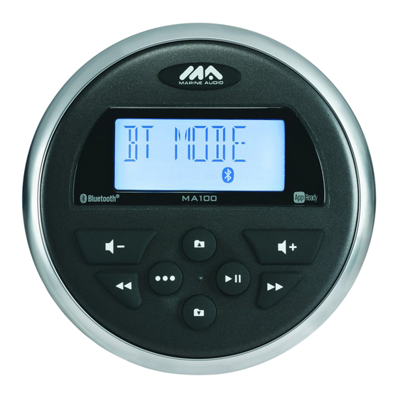
- Page 1 MA100 Owner’s Manual...
-
Page 2: Table Of Contents
MA100 CONTENTS Introduction ....................................1 Features ....................................1 Box Content ..................................1 Compliance ..................................1 Safety Information ................................2 Installation ....................................3 Mounting the Radio................................3 Auxiliary Input ..................................4 Line Output ..................................4 Wiring Diagram ..................................5 Operation....................................6 Basic Functions ................................... -
Page 3: Introduction
USB MP3/WMA Player Rear Auxiliary Audio Output 4-Channel Amplified Audio Output Bluetooth (Supports A2DP and AVRCP) Box Content MA100 Radio Radio Mounting Bracket Screw Posts (x2) Locking Hex Nuts (x2) Washers (x2) ... -
Page 4: Safety Information
MA100 Safety Information To ensure full satisfaction with the product, please read the entire instruction manual. Keep instructions for future reference. Follow all operation guidelines and adhere to all safety warnings and cautions to ensure safe use. -
Page 5: Installation
MA100 INSTALLATION Mounting the Radio Choose a mounting location on the dash board or instrument panel that will allow room behind to run radio cables to the power source. Consider how you will use the AUX IN, LINE OUT and USB connectors and route the appropriate extension cables to an accessible area. -
Page 6: Auxiliary Input
MA100 Auxiliary Input Connect a portable audio device to the Audio Input (AUX IN RIGHT/LEFT) on the back of the unit using RCA cables. Line Output The Line Out connectors (LINE OUT RIGHT/LEFT) on the back of the unit output a line-level analog signal. Use this output to... -
Page 7: Wiring Diagram
MA100 Wiring Diagram PIN NO. WIRE COLOR DESCRIPTION PURPLE RIGHT REAR SPEAKER (+) PURPLE/BLACK RIGHT REAR SPEAKER () GREEN LEFT REAR SPEAKER (+) GREEN/BLACK LEFT REAR SPEAKER (-) BLUE POWER AMP REMOTE BLACK GROUND ACC +12V Note: Do not connect the red wire to a... -
Page 8: Operation
MA100 OPERATION Basic Functions Power Press the JENSEN power button (1) to turn the unit on/off. Restore Factory Settings Perform the following steps to reset the radio to factory default settings: Press and hold the power button (1) to display the software version. -
Page 9: Usb Mode
MA100 With the display showing the current tuning mode, press the VOL - or VOL+ button (2, 3) to change between USA/EURO. Press the JENSEN power button (1) to confirm your selection. Frequency Tuning Press the l<< or >>l button (6, 7) to fine tune the radio frequency. -
Page 10: Bluetooth Operation
LOCK/UNLOCK: The MA100 can store up to 5 devices for Bluetooth connection. The devices are stored in a FIFO (First In First Out) order. To prevent a device from being bumped from the list when more than 5 devices are used, you can lock the device. - Page 11 Before you begin, consult the owner’s manual for the Bluetooth device you want to pair with the MA100. Make sure the device is on and ready to receive a signal from the MA100. With the MA100 in Bluetooth Audio mode, press and hold the MODE (8) button.
-
Page 12: App Operation
MA100 APP OPERATION JENSEN® Specialty Controller is the ultimate wireless remote control for your JENSEN stereo system. Store away your old remotes and enjoy the convenience of all the primary functions of your JENSEN stereo right from your phone or tablet by... -
Page 13: Troubleshooting
MA100 TROUBLESHOOTING Table 1: Troubleshooting Problem Solution No power If the power supply is connected to the vehicle accessory circuits but the engine is not on, switch the ignition key to “ACC” Fuse may be blown. Replace with 10AMP ATO fuse. -
Page 14: Specifications
MA100 SPECIFICATIONS General Power Supply Requirements ............DC 12 Volts, Negative Ground Operating Voltage . - Page 15 ASA Electronics Corporation www.asaelectronics.com www.jensenheavyduty.com ©2015 ASA Electronics Corporation v. 270515...
Need help?
Do you have a question about the MA100 and is the answer not in the manual?
Questions and answers