
Related Manuals for Gigabyte GA-P43-ES3G


Summary of Contents for Gigabyte GA-P43-ES3G
- Page 1 GA-P43-ES3G LGA775 socket motherboard for Intel Core processor family/ ® Intel Pentium processor family/Intel Celeron processor family ® ® ® ® User's Manual Rev. 1001 12ME-P43ES3G-1001R...
-
Page 3: Identifying Your Motherboard Revision
GIGABYTE's prior written permission. Documentation Classifications In order to assist in the use of this product, GIGABYTE provides the following types of documentations: For quick set-up of the product, read the Quick Installation Guide included with the product. -
Page 4: Table Of Contents
Box Contents ... 6 Optional Items... 6 GA-P43-ES3G Motherboard Layout ... 7 Block Diagram... 8 Chapter 1 Hardware Installation ... 9 Installation Precautions ... 9 Product Specifications ... 10 Installing the CPU and CPU Cooler ... 13 1-3-1 Installing the CPU ... 13 1-3-2 Installing the CPU Cooler ... - Page 5 Chapter 3 Drivers Installation ... 57 Installing Chipset Drivers ... 57 Application Software... 58 Technical Manuals ... 58 Contact ... 59 System ... 59 Download Center... 60 Chapter 4 Unique Features ... 61 Xpress Recovery2 ... 61 BIOS Update Utilities ... 66 4-2-1 Updating the BIOS with the Q-Flash Utility ...
-
Page 6: Box Contents
Box Contents GA-P43-ES3G motherboard Motherboard driver disk User's Manual Quick Installation Guide One IDE cable and one floppy disk drive cable Two SATA 3Gb/s cables I/O Shield • The box contents above are for reference only and the actual items shall depend on product package you obtain. -
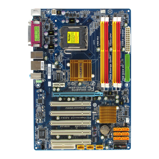
Page 7: Ga-P43-Es3G Motherboard Layout
GA-P43-ES3G Motherboard Layout KB_MS ATX_12V R_USB SYS_FAN1 USB_LAN AUDIO F_AUDIO PCIEX1 PCIEX16 RTL8111C PCI1 PCI2 CODEC PCI3 SPDIF_O PCI4 IT8718 PCI5 CD_IN LGA775 Intel ® GA-P43-ES3G M_BIOS B_BIOS F_USB3 F_USB2 F_USB1 - 7 - CPU_FAN JMicron 368 SYS_FAN2 Intel ICH10 ®... -
Page 8: Block Diagram
Block Diagram PCIe CLK (100 MHz) PCI Express x16 ATA-133/100/66/33 IDE Channel PCI Express Bus 1 PCI Express x1 PCIe CLK (100 MHz) PCI Bus IT8208M 5 PCI PCI CLK (33 MHz) LGA775 Processor Host Interface Intel ® JMicron Intel ICH10 ®... -
Page 9: Chapter 1 Hardware Installation
Chapter 1 Hardware Installation Installation Precautions The motherboard contains numerous delicate electronic circuits and components which can become damaged as a result of electrostatic discharge (ESD). Prior to installation, carefully read the user's manual and follow these procedures: Prior to installation, do not remove or break motherboard S/N (Serial Number) sticker or •... -
Page 10: Product Specifications
Product Specifications Support for an Intel Intel Intel Intel Intel (Go to GIGABYTE's website for the latest CPU support list.) L2 cache varies with CPU Front Side Bus 1600(O.C.)/1333/1066/800 MHz FSB Chipset North Bridge: Intel South Bridge: Intel Memory 4 x 1.8V DDR2 DIMM sockets supporting up to 16 GB of system memory... - Page 11 Internal Connectors 1 x 24-pin ATX main power connector 1 x 4-pin ATX 12V power connector 1 x floppy disk drive connector 1 x IDE connector 6 x SATA 3Gb/s connectors 1 x CPU fan header 2 x system fan headers 1 x front panel header 1 x front panel audio header 1 x CD In connector...
- Page 12 (Note 4) Available functions in EasyTune may differ by motherboard model. (Note 5) Due to the hardware limitation, you must install the Intel Core 2 Duo/ Pentium Dual-Core/ Celeron Dual-Core/ Celeron 400 Series CPU to enable support for Easy Energy Saver. GA-P43-ES3G Motherboard (Note 4) (Note 5) Windows Vista/XP ®...
-
Page 13: Installing The Cpu And Cpu Cooler
Read the following guidelines before you begin to install the CPU: • Make sure that the motherboard supports the CPU. (Go to GIGABYTE's website for the latest CPU support list.) • Always turn off the computer and unplug the power cord from the power outlet before installing the CPU to prevent hardware damage. - Page 14 Step 5: Once the CPU is properly inserted, replace the load plate and push the CPU socket lever back into its locked position. GA-P43-ES3G Motherboard Step 2: Lift the metal load plate from the CPU socket. (DO NOT touch socket contacts.)
-
Page 15: Installing The Cpu Cooler
1-3-2 Installing the CPU Cooler Follow the steps below to correctly install the CPU cooler on the motherboard. (The following procedure uses Intel boxed cooler as the example cooler.) ® Step 1: Apply an even and thin layer of thermal grease on the surface of the installed CPU. -
Page 16: Installing The Memory
• Make sure that the motherboard supports the memory. It is recommended that memory of the same capacity, brand, speed, and chips be used. (Go to GIGABYTE's website for the latest memory support list.) • Always turn off the computer and unplug the power cord from the power outlet before installing the memory to prevent hardware damage. -
Page 17: Installing A Memory
1-4-2 Installing a Memory Before installing a memory module , make sure to turn off the computer and unplug the power cord from the power outlet to prevent damage to the memory module. DDR2 DIMMs are not compatible to DDR DIMMs. Be sure to install DDR2 DIMMs on this motherboard. -
Page 18: Installing An Expansion Card
• Removing the Card: Press the white latch at the end of the PCI Express x16 slot to release the card and then pull the card straight up from the slot. GA-P43-ES3G Motherboard PCI Express x1 Slot PCI Express x16 Slot PCI Slot •... -
Page 19: Back Panel Connectors
Back Panel Connectors PS/2 Keyboard and PS/2 Mouse Port Use the upper port (green) to connect a PS/2 mouse and the lower port (purple) to connect a PS/2 keyboard. Parallel Port Use the parallel port to connect devices such as a printer, scanner and etc. The parallel port is also called a printer port. - Page 20 To enable 7.1-channel audio, you have to use an HD front panel audio module and enable the multi-channel audio feature through the audio driver. Refer to the instructions on setting up a 2/4/5.1/7.1-channel audio configuration in Chapter 5, "Configuring 2/4/5.1/7.1-Channel Audio." GA-P43-ES3G Motherboard - 2 0 -...
-
Page 21: Internal Connectors
Internal Connectors ATX_12V CPU_FAN SYS_FAN1/SYS_FAN2 SATA2_0/1/2/3/4/5 PWR_LED Read the following guidelines before connecting external devices: • First make sure your devices are compliant with the connectors you wish to connect. • Before installing the devices, be sure to turn off the devices and your computer. Unplug the power cord from the power outlet to prevent damage to the devices. - Page 22 When using a 2x12 power supply, remove the protective cover from the main power connector on the motherboard. Do not insert the power supply cable into pins under the protective cover when using a 2x10 power supply. GA-P43-ES3G Motherboard ATX_12V ATX : Pin No.
- Page 23 3/4) CPU_FAN/SYS_FAN1/SYS_FAN2(Fan Headers) The motherboard has a 4-pin CPU fan header (CPU_FAN), a 3-pin (SYS_FAN 1) and a 4-pin (SYS_FAN2) system fan headers. Most fan headers possess a foolproof insertion design. When connecting a fan cable, be sure to connect it in the correct orientation (the black connector wire is the ground wire).
- Page 24 7) SATA2_0/1/2/3/4/5 (SATA 3Gb/s Connectors, Controlled by ICH10) The SATA connectors conform to SA TA 3Gb/s standard and are compatible with SA TA 1.5Gb/s standard. Each SATA connector supports a single SA TA device. GA-P43-ES3G Motherboard SATA2_3 SATA2_0 SATA2_4...
-
Page 25: Battery
8) PWR_LED (System Power LED Header) This header can be used to connect a system power LED on the chassis to indicate system power status. The LED is on when the system is operating. The LED keeps blinking when the system is in S1 sleep state. -
Page 26: F_Panel
LED, hard drive activity LED, speaker and etc. When connecting your chassis front panel module to this header, make sure the wire assign- ments and the pin assignments are matched correctly. GA-P43-ES3G Motherboard Message/Power/ Connects to the power status indicator on the chassis front panel. The LED is on when the system is operating. -
Page 27: Front Panel Audio Header
11) F_AUDIO (Front Panel Audio Header) The front panel audio header supports Intel High Definition audio (HD) and AC'97 audio. You may connect your chassis front panel audio module to this header. Make sure the wire assignments of the module connector match the pin assignments of the motherboard header. Incorrect connection between the module connector and the motherboard header will make the device unable to work or even damage it. - Page 28 • Do not plug the IEEE 1394 bracket (2x5-pin) cable into the USB header. • Prior to installing the USB bracket, be sure to turn off your computer and unplug the power cord from the power outlet to prevent damage to the USB bracket. GA-P43-ES3G Motherboard Pin No. Pin No.
-
Page 29: Chassis Intrusion Header
15) CI (Chassis Intrusion Header) This motherboard provides a chassis detection feature that detects if the chassis cover has been removed. This function requires a chassis with chassis intrusion detection design. 16) CLR_CMOS (Clearing CMOS Jumper) Use this jumper to clear the CMOS values (e.g. date information and BIOS configurations) and reset the CMOS values to factory defaults. - Page 30 GA-P43-ES3G Motherboard - 3 0 -...
-
Page 31: Chapter 2 Bios Setup
To see more advanced BIOS Setup menu options, you can press <Ctrl> + <F1> in the main menu of the BIOS Setup program. To upgrade the BIOS, use either the GIGABYTE Q-Flash or @BIOS utility . Q-Flash allows the user to quickly and easily upgrade or back up BIOS without entering the •... -
Page 32: Startup Screen
BIOS Setup settings. You can access Boot Menu again to change the first boot device setting as needed. <End>: Q-Flash Press the <End> key to access the Q-Flash utility directly without having to enter BIOS Setup first. GA-P43-ES3G Motherboard - 3 2 - Function Keys Function Keys... -
Page 33: The Main Menu
The Main Menu Once you enter the BIOS Setup program, the Main Menu (as shown below) appears on the screen. Use arrow keys to move among the items and press <Enter> to accept or enter a sub-menu. (Sample BIOS Version: E28) CMOS Setup Utility-Copyright (C) 1984-2008 Award Software MB Intelligent Tweaker(M.I.T.) Standard CMOS Features... - Page 34 (Pressing <F10> can also carry out this task.) Exit Without Saving Abandon all changes and the previous settings remain in effect. Pressing <Y> to the confirmation message will exit BIOS Setup. (Pressing <Esc> can also carry out this task.) GA-P43-ES3G Motherboard - 3 4 -...
-
Page 35: Mb Intelligent Tweaker(M.i.t.)
MB Intelligent Tweaker(M.I.T.) CMOS Setup Utility-Copyright (C) 1984-2008 Award Software Robust Graphics Booster CPU Clock Ratio (Note 1) (Note 1) Fine CPU Clock Ratio CPU Frequency ******** Clock Chip Control ******** >>>>> Standard Clock Control CPU Host Clock Control x CPU Host Frequency (Mhz) PCI Express Frequency (Mhz) ******** DRAM Performance Control Performance Enhance... - Page 36 Uses Profile 2 settings. (Note 1) This item appears only if you install a CPU that supports this feature. (Note 2) This item appears only if you install a memory module that supports this feature. GA-P43-ES3G Motherboard (Note 1) ********...
- Page 37 (G)MCH Frequency Latch Allows you to fix the chipset frequency at system bootup. Options for adjusting memory multiplier below may differ according to the fixed frequency. Options are: Auto (default), 200MHz, 266MHz, 333MHz, 400MHz. System Memory Multiplier (SPD) Allows you to set the system memory multiplier. Options are dependent on CPU FSB and the (G)MCH Frequency Latch settings.
- Page 38 Phase3 Adjustment Options are: Auto (default), 0-Normal, 1-Advanced. Trd2rd(Different Rank) Options are: Auto (default), 1~15. Twr2wr(Different Rank) Options are: Auto (default), 1~15. Twr2rd(Different Rank) Options are: Auto (default), 1~15. GA-P43-ES3G Motherboard Channel A Timing Settings Auto Auto Auto Auto Auto Auto...
- Page 39 Trd2wr(Same/Diff Rank) Options are: Auto (default), 1~15. DIMM1 Clock Skew Control Options are: Auto (default), +800ps~-700ps. DIMM2 Clock Skew Control Options are: Auto (default), +800ps~-700ps. DDR Write Training Allows you to determine whether to fine-tune memory parameters to enhance memory compatibility. Auto Lets the BIOS decide whether to enable this function.
- Page 40 CPU Vcore The default is Auto. CPU Termination The default is Auto. CPU Reference The default is Auto. >>> MCH/ICH MCH Core The default is Auto. >>> DRAM DRAM Voltage The default is Auto. GA-P43-ES3G Motherboard ******** - 4 0 -...
-
Page 41: Standard Cmos Features
Standard CMOS Features CMOS Setup Utility-Copyright (C) 1984-2008 Award Software Date (mm:dd:yy) Time (hh:mm:ss) IDE Channel 0 Master IDE Channel 0 Slave IDE Channel 1 Master IDE Channel 1 Slave IDE Channel 2 Master IDE Channel 3 Master IDE Channel 4 Master IDE Channel 4 Slave Drive A Floppy 3 Mode Support... - Page 42 Base Memory Also called conventional memory. Typically, 640 KB will be reserved for the MS-DOS operating system. Extended Memory The amount of extended memory. Total Memory The total amount of memory installed on the system. GA-P43-ES3G Motherboard - 4 2 -...
-
Page 43: Advanced Bios Features
Advanced BIOS Features CMOS Setup Utility-Copyright (C) 1984-2008 Award Software Hard Disk Boot Priority First Boot Device Second Boot Device Third Boot Device Password Check HDD S.M.A.R.T. Capability (Note) CPU Multi-Threading (Note) Limit CPUID Max. to 3 No-Execute Memory Protect CPU Enhanced Halt (C1E) C2/C2E State Support (Note) - Page 44 With virtualization, one computer system can function as multiple virtual systems. (Default: Enabled) (Note) This item is pres ent only if you install a CPU that supports this feature. For more information about Intel CPUs' unique features, please visit Intel's website. GA-P43-ES3G Motherboard (Note) (Note) (Note) Execute Disable Bit function.
- Page 45 Allows you to set a delay time for the BIOS to initialize the hard drive as the system boots up. The adjustable range is from 0 to 15 seconds. (Default: 0) Full Screen LOGO Show Allows you to determine whether to display the GIGABYTE Logo at system startup. Disabled displays normal POST message. (Default: Enabled) Init Display First Specifies the first initiation of the monitor display from the installed PCI graphics card or the PCI Express graphics card.
-
Page 46: Integrated Peripherals
When the onboard LAN function and Green LAN are enabed, the system will dynamically detects if LAN cable(s) is connected or not. If not, the corresponding LAN controller will be disabled automatically. (Default: Disabled) GA-P43-ES3G Motherboard Integrated Peripherals [Disabled] [Disabled]... - Page 47 SMART LAN (LAN Cable Diagnostic Function) CMOS Setup Utility-Copyright (C) 1984-2008 Award Software Start detecting at Port... Part1-2 Status = Open Part3-6 Status = Open Part4-5 Status = Open Part7-8 Status = Open : Move Enter: Select F5: Previous Values This motherboard incorporates cable diagnostic feature designed to detect the status of the attached LAN cable.
- Page 48 USB Mouse Function Allows USB mouse to be used in MS-DOS. (Default: Disabled) USB Storage Function Determines whether to detect USB storage devices, including USB flash drives and USB hard drives during the POST. (Default: Enabled) GA-P43-ES3G Motherboard - 4 8 -...
-
Page 49: Power Management Setup
Power Management Setup CMOS Setup Utility-Copyright (C) 1984-2008 Award Software ACPI Suspend Type Soft-Off by PWR-BTTN PME Event Wake Up Power On by Ring Resume by Alarm x Date (of Month) Alarm x Time (hh:mm:ss) Alarm (Note) HPET Support (Note) HPET Mode Power On By Mouse Power On By Keyboard... - Page 50 The system is turned on upon the return of the AC power. Memory The system returns to its last known awake state upon the return of the AC power. (Note) Supported on Windows GA-P43-ES3G Motherboard Vista ; select 64-bit mode when you install 64-bit ® ® Vista operating system only.
-
Page 51: Pnp/Pci Configurations
PnP/PCI Configurations CMOS Setup Utility-Copyright (C) 1984-2008 Award Software PCI1 IRQ Assignment PCI2 IRQ Assignment PCI3 IRQ Assignment PCI4 IRQ Assignment PCI5 IRQ Assignment : Move Enter: Select F5: Previous Values PCI1 IRQ Assignment Auto 3,4,5,7,9,10,11,12,14,15 PCI2 IRQ Assignment Auto 3,4,5,7,9,10,11,12,14,15 PCI3 IRQ Assignment Auto... -
Page 52: Pc Health Status
C/194 CPU/SYSTEM FAN Fail Warning Allows the system to emit warning sound if the CPU/system fan is not connected or fails. Check the fan condition or fan connection when this occurs. (Default: Disabled) GA-P43-ES3G Motherboard PC Health Status [Disabled] 1.316V 1.808V... - Page 53 CPU Smart FAN Control Enables or disables the CPU fan speed control function. Auto lets the BIOS decide whether to enable this function. Enabled allows the CPU fan to run at different speed according to the CPU temperature. You can adjust the fan speed with EasyT une based on system requirements. If disabled, CPU fan runs at full speed.
-
Page 54: Load Fail-Safe Defaults
Press <Enter> on this item and then press the <Y> key to load the optimal BIOS default settings. The BIOS defaults settings helps the system to operate in optimum state. Always load the Optimized defaults after updating the BIOS or after clearing the CMOS values. GA-P43-ES3G Motherboard Load Fail-Safe Defaults Load Optimized Defaults... -
Page 55: Set Supervisor/User Password
2-12 Set Supervisor/User Password CMOS Setup Utility-Copyright (C) 1984-2008 Award Software MB Intelligent Tweaker(M.I.T.) Standard CMOS Features Advanced BIOS Features Integrated Peripherals Power Management Setup PnP/PCI Configurations PC Health Status ESC: Quit F8: Q-Flash Press <Enter> on this item and type the password with up to 8 characters and then press <Enter>. You will be requested to confirm the password. -
Page 56: Save & Exit Setup
Press <Enter> on this item and press the <Y> key. This exits the BIOS Setup without saving the changes made in BIOS Setup to the CMOS. Press <N> or <Esc> to return to the BIOS Setup Main Menu. GA-P43-ES3G Motherboard Load Fail-Safe Defaults... -
Page 57: Chapter 3 Drivers Installation
Chapter 3 Drivers Installation • Before installing the drivers, first install the operating system. (The following instructions use Windows XP as the example operating system.) • After installing the operating system, insert the motherboard driver disk into your optical drive. The driver Autorun screen is automatically displayed which looks like that shown in the screen shot below. -
Page 58: Application Software
Application Software This page displays all the utilities and applications that GIGABYTE develops and some free software. You can click the Install button on the right of an item to install it. Technical Manuals This page provides GIGABYTE's application guides, content descriptions for this driver disk, and the motherboard manuals. -
Page 59: Contact
Contact Click the URL on this page to link to the GIGABYTE Web site. Or read the last page of th is manual to check the contact information for GIGABYTE Taiwan headquarter or worldwide branch of fices. System This page provides the basic system information. -
Page 60: Download Center
Download Center To update the BIOS, drivers, or applications, click the Download Center button to link to the GIGABYTE Web site. The latest version of the BIOS, drivers, or applications will be displayed. GA-P43-ES3G Motherboard - 6 0 -... -
Page 61: Chapter 4 Unique Features
Chapter 4 Unique Features Xpress Recovery2 Before You Begin: • Xpress Recovery2 will check the first physical hard drive* for the operating system. Xpress Recovery2 can only back up/restore the first physical hard drive that has the operating system installed. •... -
Page 62: Installation And Configuration
Recovery2 (10 GB or more is recommended; actual size requirements vary, depending on the amount of data) (Figure 2). Figure 1 3. Select a file system (for example, NTFS) and begin the installation of the operating system (Figure 3). Figure 3 GA-P43-ES3G Motherboard Figure 2 - 6 2 -... - Page 63 4. After the operating system is installed, right-click the My Computer icon on your desktop and select Manage (Figure 4). Go to Computer Management to check disk allocation. Xpress Recovery2 will save the backup file to the unallocated space (black stripe along the top)(Figure 5). Please note that if there is no enough unallocated space, Xpress Recovery2 cannot save the backup file.
- Page 64 Xpress Recovery 2 will begin the backup process (Figure 11). Figure 10 3. When finished, go to Disk Management to check disk allocation. Figure 12 GA-P43-ES3G Motherboard Figure 8 Figure 9 Figure 11 Xpress Recovery2 will automatically create a new partition to store the backup image file.
- Page 65 D. Using the Restore Function in Xpress Recovery2 Select RESTORE to restore the backup to your hard drive in case the system breaks down. The RESTORE option will not be present if no backup is created before (Figure 13, 14). Figure 13 E.
-
Page 66: Bios Update Utilities
4-2-1 Updating the BIOS with the Q-Flash Utility A. Before You Begin: 1. From GIGABYTE's website, download the latest compressed BIOS update file that matches your motherboard model. 2. Extract the file and save the new BIOS file (e.g. P43ES3G.F1) to your floppy disk, USB flash drive, or hard drive. - Page 67 B. Updating the BIOS When updating the BIOS, choose the location where the BIOS file is saved. The follow procedure assumes that you save the BIOS file to a floppy disk. Step 1: 1. Insert the floppy disk containing the BIOS file into the floppy disk drive. In the main menu of Q-Flash, use the up or down arrow key to select Update BIOS from Drive and press <Enter>.
- Page 68 F8: Q-Flash Step 6: Select Save & Exit Setup and then press <Y> to save settings to CMOS and exit BIOS Setup. The procedure is complete after the system restarts. GA-P43-ES3G Motherboard Load Fail-Safe Defaults Load Optimized Defaults Set Supervisor Password...
-
Page 69: Updating The Bios With The @Bios Utility
BIOS or a system that is unable to start. 3. Do not use the G.O.M. (GIGABYTE Online Management) function when using @BIOS. 4. GIGABYTE product warranty does not cover any BIOS damage or system failure resulting from an inadequate BIOS flashing. -
Page 70: Easytune 6
EasyTune 6 GIGABYTE's EasyTune 6 is a simple and easy-to-use interface that allows users to fine-tune their system settings or do overclock/overvoltage in Windows environment. The user-friendly EasyTune 6 interface also includes tabbed pages for CPU and memory information, lettings users read their system- related information without the need to install additional software. -
Page 71: Easy Energy Saver
The Easy Energy Saver Interface A. Meter Mode In Meter Mode, GIGABYTE Easy Energy Saver shows how much power they have saved in a set period of time. Meter Mode - Button Information Table Button Description... - Page 72 Energy Saver is under the enable status, and power savings meter is unable to reset to zero. (Note 5) Easy Energy Saver Meter will automatically reset when the total power saving reaches 99999999 Watts. GA-P43-ES3G Motherboard (Note 4) (Note 3)
-
Page 73: Chapter 5 Appendix
Chapter 5 Appendix Configuring Audio Input and Output 5-1-1 Configuring 2/4/5.1/7.1-Channel Audio The motherboard provides three audio jacks on the back panel which support 2/4/5.1/7.1 ture to the right shows the default audio jack assignments. The integrated HD (High Definition) audio provides jack retasking capability that allows the user to change the func- tion for each jack through the audio driver. - Page 74 Everytime you connect an audio device to an audio jack, the Connected device box appears. Select the device according to the type of device you connect. Then click OK to complete the configuration. GA-P43-ES3G Motherboard 7.1-Channel Speakers: - 7 4 - Front Speaker Out...
- Page 75 B. Configuring Sound Effect: You may configure an audio environment on the Sound Effect tab. C. Activating an AC'97 Front Panel Audio Module: If your chassis provides an AC'97 front panel audio module, to activate the AC'97 functionality, click the tool icon on the Audio I/O tab.
-
Page 76: Configuring S/Pdif Out
Click OK to complete the configuration. (Note) The actual location of the SPDIF Out connector may differ by model. GA-P43-ES3G Motherboard Connect a S/PDIF coaxial cable to an external decoder for transmitting the S/PDIF digital audio signals. - 7 6 -... -
Page 77: Configuring Microphone Recording
5-1-3 Configuring Microphone Recording Step 1: After installing the audio driver, the Audio Manager icon will appear in your system tray. Double-click the icon to access the Audio Control Panel. Step 2: Connect your microphone to the Mic in jack (pink) on the back panel or the Line in jack on the front panel. - Page 78 Based on the audio specifications, to adjust the re- cording sound, use the Recording option to set the recording sound for your recording device(s) altogether. GA-P43-ES3G Motherboard OK to Select Realtek HD Audio Input in the Mixer device list Recording Control...
-
Page 79: Using The Sound Recorder
Step 6: To raise the recording and playing sound for the microphone, go to Options in Master Volume and select Advanced Controls. Click the Advanced button under a volume control option (e.g. Front Green In, Front Pink In). In the Other Controls field, select the 1 Microphone Boost check box. -
Page 80: Troubleshooting
1 long, 2 short: Monitor or graphics card error 1 long, 3 short: Keyboard error 1 long, 9 short: BIOS ROM error Continuous long beeps: Graphics card not inserted properly Continuous short beeps: Power error GA-P43-ES3G Motherboard - 8 0 -... -
Page 81: Troubleshooting Procedure
5-2-2 Troubleshooting Procedure If you encounter any troubles during system startup, follow the troubleshooting procedure below to solve the problem. Turn off the power. Remove all peripherals, connecting cables, and power cord etc. Make sure the motherboard does not short-circuit with the chassis or other metal objects. - Page 82 If the procedure above is unable to solve your problem, contact the place of purchase or local dealer for help. Or go to the Support\Technical Service Zone page to submit your question. Our customer service staff will reply you as soon as possible. GA-P43-ES3G Motherboard - 8 2 - The power supply, CPU or CPU socket might fail.
-
Page 83: Regulatory Statements
"end of life" product. Restriction of Hazardous Substances (RoHS) Directive Statement GIGABYTE products have not intended to add and safe from hazardous substances (Cd, Pb, Hg, Cr+6, PBDE and PBB). The parts and components have been carefully selected to meet RoHS requirement. - Page 84 China Restriction of Hazardous Substances Table The following table is supplied in compliance with China's Restriction of Hazardous Substances (China RoHS) requirements: GA-P43-ES3G Motherboard - 8 4 -...
- Page 85 - 85 - Appendix...
- Page 86 GA-P43-ES3G Motherboard - 8 6 -...
- Page 87 FAX: +86-28-85256822 Xian TEL: +86-29-85531943 FAX: +86-29-85510930 Shenyang TEL: +86-24-83992901 FAX: +86-24-83992909 GIGABYTE TECHNOLOGY (INDIA) LIMITED - India WEB address : http://www.gigabyte.in Saudi Arabia WEB address : http://www.gigabyte.com.sa GIGABYTE TECHNOLOGY PTY. LTD. - Australia WEB address : http://www.gigabyte.com.au - 87 -...
- Page 88 WEB address : http://www.gigabyte.co.yu Kazakhstan WEB address : http://www.giga-byte.kz You may go to the GIGABYTE website, select your language in the language list on the top right corner of the website. To submit a technical or non-technical (Sales/ Marketing) question, please link to : http://ggts.gigabyte.com.tw...
Need help?
Do you have a question about the GA-P43-ES3G and is the answer not in the manual?
Questions and answers