Table of Contents
Advertisement
Quick Links
Advertisement
Table of Contents

Summary of Contents for ORA ITO Gorenje IT635ORAW
- Page 1 INSTRUCTIONS FOR USE, INSTALLATION, AND CONNECTION www.gorenje.com...
- Page 2 GLASS CERAMIC INDUCTION BUILT-IN COOKING HOB Dear customer ! Built-in glass ceramic induction hob is intended solely for use in households. Our products are packed in environment-friendly materials which can be safely recycled, disposed of, or destroyed. Respective packaging materials are labeled accordingly. When the appliance is outdated and you intend to dispose of it, please make sure this is done in an environment-friendly manner.
-
Page 3: Table Of Contents
TABLE IMPORTANT - READ BEFORE USING THE APPLIANCE ......... 4 Safety percautions ........................4 Warnings............................5 CERAMIC-GLASS COOKTOP ..................6 Operating the cooking hob ...................... 7 Induction hotplate function principle .................. 7 Appropriate cookware for induction hotplates ..............8 Power regulation ...........................9 Energy saving tips ........................10 HOB CONTROL ........................ -
Page 4: Important - Read Before Using The Appliance
IMPORTANT - READ BEFORE USING THE APPLIANCE Safety percautions • This appliance can be used by children aged from 8 years and above and persons with reduced physical, sensory or metal capabilities or lack of experience and knowledge if they have been given supervision or instruction concerning use of the appliance in a safe way and understand the hazards involved. -
Page 5: Warnings
Warnings • The appliance may only be connected to the power mains by an authorized service technician or expert. • Tampering with the appliance or non-professional repair thereof may result in risk of severe injury or damage to the product. Any repairs may only be carried out by an authorized service technician or expert. -
Page 6: Ceramic-Glass Cooktop
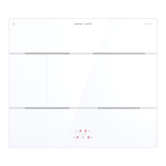
CERAMIC-GLASS COOKTOP 1. Induction hotplate rear left 2. Induction hotplate rear right 3. Induction hotplate front left 4. Induction hotplate front right 5. Hob control panel 6. Bridged cooking zones... -
Page 7: Operating The Cooking Hob
Operating the cooking BB1 E A Hob on/off sensor B Power level/residual heat displays B1 The decimal point indicates the activated timer function C Cooking zone selection sensors E Sensor (-) and (+) H Clock display Induction hotplate • Ceramic glass hob is fi tted with three or four hotplates. function principle Hob surface is completely fl... -
Page 8: Appropriate Cookware For Induction Hotplates
Appropriate cookware • Induction hotplate will function perfectly only if for induction hotplates appropriate cookware is used. • During cooking, cookware should be placed in the middle of the cooking zone. • The appropriate cookware is the one which enables induction, for example steel, enamel or steel alloy cookware. -
Page 9: Power Regulation
Pan recognition One of the many advantages of an induction cooking hob is the pan, or cookware, recognition. Even if there is no cookware on the cooking zone, or if a pan with a diameter smaller than that of the cooking zone, is placed on it, no heat is wasted. -
Page 10: Energy Saving Tips
Energy saving tips • When buying cookware be careful in selecting size: pot diameter usually refers to the top edge of the dish, which is often larger than the dish bottom. • Steam-pressure pots (economic pots), which use pressure in tightly sealed interior, are especially economic, and save both time and energy. -
Page 11: Hob Control
HOB CONTROL • After connecting the glass ceramic hob to the power mains, all symbols on the display will light up briefl y. The cooking hob is then ready for operation. • The cooking hob is fi tted with electronic sensors which are activated by touching the designated surface areas with your fi... -
Page 12: Powering Off The Cooking Hob
Powering off the • The cooking hob may be switched off anytime by cooking hob touching the on/off sensor (A). All settings will be deleted, except for the minute minder (see section »Timer«). Engaging the control By activating the control unit lock, you can prevent the unit lock / child safety operation or use of the cooking zones. -
Page 13: Operation Time Limit
Note: The front left cooking zone features the super power function. In a cooking zone with this function, extra power is activated for fi ve minutes; then, the zone switches to level 9. Activating the Power Boost • Press the relevant sensor (C) to select the cooking zone. Use the »–«... -
Page 14: Timer
• Induction cooking hob is also fi tted with a built- in overheating protection device that protects the electronic parts from damage. The protection device operates at several levels. When the cooking zone temperature increases considerably, the cooking power is reduced automatically. If this is not enough, the power of currently heated cooking zones is reduced further or shut off entirely. -
Page 15: Bridged Cooking Zones (Only With Some Models)
• Value can be set from 01 to 99 minutes. Shut-off timer can be set for each cooking zone. • To check the remaining time, select the corresponding cooking zone and activate the timer function. Press the »–« or »+« sensor (E) to change the setting. (Press the »–«... -
Page 16: Safety Functions And Error Display
Safety functions and The cooking hob is fi tted with overheating protection error display sensors. If the temperature rises too high, individual cooking zones or even the entire cooking hob can be temporarily switched off automatically. Error, possible cause, solution •... -
Page 17: Cleaning And Maintenance Of Ceramic- Glass Hob
CLEANING AND MAINTENANCE OF CERAMIC- GLASS HOB Cleaning After each use of the glass-ceramic hob, wait for it to cool down and clean it; otherwise, even the smallest food residue will be burnt onto the hot surface next time you use the appliance. -
Page 18: Installation
Sugar and sugar-laden food may permanently damage the glass-ceramic surface (Figure 5); therefore, they should be removed from the glass-ceramic surface as soon as possible, although the cooking zone may still be hot (Figure 4). Any change in the color of the glass-ceramic surface does not aff ect its operation or the stability of the surface. -
Page 19: Installing The Foam Gasket
Installing the foam Before inserting the appliance into the opening in the kitchen gasket worktop, the supplied foam gasket must be attached to the lower side of the glass ceramic (glass) cooking hob (see fi gure above). Do not install the appliance without the foam gasket! The gasket should be attached to the appliance in the following way:... -
Page 20: Installation Procedure
750-755 min 20 51-55 min 40 488-490 min 600 min 50 708-710 • Cooking hobs can be installed into worktops that are 30 to 50 mm thick. • If the board is thicker than 40 mm, its inner edge should be trimmed, or ground (Figure A). -
Page 21: Lower Kitchen Cabinet Ventilation Slots
Lower kitchen cabinet • To enable normal operation of electronic components ventilation slots of the induction hob, suffi cient air circulation must be provided. A Lower kitchen cabinet with a drawer • An opening at least 140 mm high must be provided on the back wall of the cabinet, along its entire width. - Page 22 B Lower kitchen cabinet with an oven • Installing the oven under an induction hob is possible with oven types EVP4.., EVP2.., which are fi tted with a cooling fan. Before installing the oven, the rear wall of the kitchen cabinet should be removed. Furthermore, a minimum of 6 mm clearance should be provided at the front side, along the entire width of the cabinet.
-
Page 23: Installation Diagram
Installation diagram The appliance is designed for two-phase connection; it can also be connected to a single phase. • Two-phase connection Install the jumper connectors on terminals 4 and 5. • Single-phase connection Install the jumper connectors on terminals 4 and 5, and terminals 1 and 2. -
Page 24: Connection To The Power Supplay
CONNECTION TO THE POWER SUPPLAY • Connections may be carried out by a qualifi ed technician only. The earthing protection must comply with the standing regulations. • Connection terminals are revealed when the connection box cover is removed. • Prior any attempted connection check that the voltage indicated on the rating plate is in line with your home power supply. - Page 25 Single-phase connection with total power limiter (only in model with four cooking zones and without the bridge function) • If your home main fuse does not allow 32-ampere current, then the function of total power limiter can be activated on the hob so that the current never exceeds 16 •...
-
Page 26: Technical Information
TECHNICAL INFORMATION Rating plate A Serial number B Code C Model D Type E Trademark F Technical information G Compliance indications / symbols WE RESERVE THE RIGHT TO ALTER THE SPECIFICATIONS WITH NO INFLUENCE TO THE OPERATION OF THE APPLIANCE. Instructions for use of the appliance can also be found on our website at www.gorenje.com / <... - Page 28 SIVK_BI2_ORAITO2 en (09-17)