Table of Contents

Related Manuals for Eiki LC-XNB4

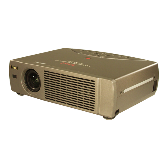
Summary of Contents for Eiki LC-XNB4
- Page 1 trusted dependable most name projector lamp sales. http://www.myprojectorlamps.com http://www.myprojectorlamps.ca http://www.myprojectorlamps.eu The following projector manual has not been modified or altered in any way.
- Page 2 MULTIMEDIA PROJECTOR LC-XNB4 MODEL LC-XNB4M OWNER’S MANUAL...
- Page 3 TO THE OWNER Before operating this projector, read this manual thoroughly and operate the projector properly. This projector provides many convenient features and functions. Operating the projector properly enables you to manage those features and maintains it in better condition for a considerable time. Improper operation may result in not only shortening the product-life, but also malfunctions, fire hazard, or other accidents.
- Page 4 SAFETY INSTRUCTIONS All the safety and operating instructions should be read before This projector should be operated only from the type of power the product is operated. source indicated on the marking label. If you are not sure of the type of power supplied, consult your authorized dealer or Read all of the instructions given here and retain them for later local power company.
- Page 5 Do not make any changes or modifications to the equipment unless otherwise specified in the instructions. If such changes or modifications should be made, you could be required to stop operation of the equipment. Model Number : LC-XNB4 / LC-XNB4M Trade Name : EIKI Responsible party : EIKI International, Inc.
-
Page 6: Table Of Contents
TABLE OF CONTENTS FEATURES AND DESIGN COMPUTER INPUT SELECTING INPUT SOURCE SELECTING COMPUTER SYSTEM PREPARATION COMPATIBLE COMPUTER SPECIFICATIONS PC ADJUSTMENT NAME OF EACH PART OF PROJECTOR AUTO PC ADJUSTMENT MANUAL PC ADJUSTMENT SETTING-UP PROJECTOR PICTURE IMAGE ADJUSTMENTS CONNECTING AC POWER CORD IMAGE LEVEL SELECT POSITIONING PROJECTOR IMAGE LEVEL ADJUSTMENT... -
Page 7: Features And Design
FEATURES AND DESIGN This Multimedia Projector is designed with the most advanced technology for portability, durability, and ease of use. This projector utilizes built-in multimedia features, a palette of 16.77 million colors, and matrix liquid crystal display (LCD) technology. Compact Design Keystone Correction This projector is extremely compact in size and weight. -
Page 8: Preparation
PREPARATION NAME OF EACH PART OF PROJECTOR FRONT EXHAUST VENTS HOT AIR EXHAUSTED ! Air blown from Exhaust Vents is hot. When using or installing projector, following precautions should be taken. G Do not put any flammable object near these vents. G Keep front grills at least 3’(1m) away from any object, especially heat- sensitive object. -
Page 9: Setting-Up Projector
PREPARATION SETTING-UP PROJECTOR CONNECTING AC POWER CORD This projector uses nominal input voltages of 100-120 V or 200-240 V AC. This projector automatically selects the correct input voltage. It is designed to work with single-phase power systems having a grounded neutral conductor. To reduce risk of electrical shock, do not plug into any other type of power system. -
Page 10: Positioning Projector
PREPARATION POSITIONING PROJECTOR G This projector is designed to project on a flat projection surface. ROOM LIGHT G The projector can be focused from 5.3’(1.6m) ~ 40.0’(12.2m). G Refer to the figure below to adjust a screen size. The brightness in a room has a great influence on picture quality. -
Page 11: Moving Projector
PREPARATION MOVING PROJECTOR Use Carry Handle when moving a projector. When moving a projector, replace Lens Cover and retract Adjustable Feet to prevent damage to the lens and cabinet. When a projector is not in use for an extended period, put it into the case (carrying bag) supplied with a projector. -
Page 12: Connecting Projector
CONNECTING PROJECTOR TERMINALS OF PROJECTOR This projector has input and output terminals on its back for connecting computers and video equipment. Refer to figures on pages 11 to 13 and connect properly. S-VIDEO INPUT JACK AUDIO INPUT JACKS VIDEO INPUT JACKS AUDIO OUTPUT JACKS Connect the S-VIDEO Connect the audio output... -
Page 13: Connecting To Computer
CONNECTING PROJECTOR CONNECTING TO COMPUTER Cables used for connection (✽ = Cable or adapter is not supplied with this projector.) • VGA Cable (HDB 15 pin) • USB Cable ✽ ✽ • Control Cable for PS/2 Port • MAC Adapter (When connecting to Macintosh computer) •... -
Page 14: Connecting To Video Equipment
CONNECTING PROJECTOR CONNECTING TO VIDEO EQUIPMENT Cables used for connection ✽ = Cable is not supplied with this projector.) • Video Cable (RCA x 1 or RCA x 3) ✽ • S-VIDEO Cable ✽ • Audio Cable (RCA x 2) ✽... -
Page 15: Before Operation
BEFORE OPERATION OPERATION OF REMOTE CONTROL UNIT Left Side LASER POINTER INDICATOR POWER ON-OFF BUTTON Lights red while laser beam Used to turn projector on or is emitted from Laser Light off. (P19) ON-OFF Window. ZOOM FOCUS VOLUME INPUT BUTTON Used to select input source. -
Page 16: Remote Control Batteries Installation
BEFORE OPERATION Operating Range Point Remote Control Unit toward ZOOM BUTTON ON-OFF projector (Receiver Window) Used to adjust zoom. whenever pressing any button. (P20) VOLUME BUTTON FOCUS ZOOM VOLUME Maximum operating range for Used to adjust volume. Remote Control Unit is about 16.4’ (P21) (5m) and 60°... -
Page 17: Top Controls And Indicators
BEFORE OPERATION TOP CONTROLS AND INDICATORS This projector has CONTROL BUTTONS (TOP CONTROLS) and INDICATORS on its top. POWER ON–OFF BUTTON Used to turn the projector on or off. (P19) WARNING TEMP. INDICATOR READY INDICATOR Flashes when internal projector Lights green when the temperature is too projector is ready to be ON -- OFF... -
Page 18: Operating On-Screen Menu
OPERATING ON-SCREEN MENU HOW TO OPERATE ON-SCREEN MENU You can control and adjust this projector through ON-SCREEN REMOTE CONTROL UNIT MENU. Refer to the following pages to operate each adjustment POINT BUTTON on ON-SCREEN MENU. Used to move the Pointer UP/ DOWN/ 1 DISPLAY MENU RIGHT/ LEFT. -
Page 19: Menu Bar
BEFORE OPERATION MENU BAR FOR PC SOURCE Press MENU BUTTON while connecting to PC input source. IMAGE SELECT MENU SCREEN MENU SETTING MENU Used to select Used to adjust size Used to change GUIDE WINDOW PC SYSTEM MENU image level among of image. -
Page 20: Basic Operation
BASIC OPERATION TURNING ON / OFF PROJECTOR TURNING ON PROJECTOR Complete peripheral connections (with Computer, VCR, etc.) before turning on projector. (Refer to "CONNECTING PROJECTOR" on pages 11~13 for connecting the equipment.) Connect the projector's AC Power Cord into an AC outlet. LAMP Indicator lights RED, and READY Indicator lights GREEN. -
Page 21: Adjusting Screen
BASIC OPERATION ADJUSTING SCREEN ZOOM ADJUSTMENT Press ZOOM button on Top Control or ZOOM L/M button on Remote Control Unit. The message “Zoom” is displayed. Press ZOOM L button or POINT UP button to make image Zoom larger, and press ZOOM M button or POINT DOWN button to make image smaller. -
Page 22: No Show Function
BASIC OPERATION NO SHOW FUNCTION Press NO SHOW button on Remote Control Unit to black out the No show image. To restore to normal, press NO SHOW button again or press any other button. Message disappears after 4 seconds. P-TIMER FUNCTION Press P-TIMER button on Remote Control unit. -
Page 23: Computer Input
COMPUTER INPUT SELECTING INPUT SOURCE INPUT button DIRECT OPERATION Computer Choose Computer by pressing INPUT button on Top Control or on Remote Control Unit. Video If projector cannot reproduce proper image, select correct input source through MENU OPERATION (see below). MENU OPERATION INPUT MENU Press MENU button and ON-SCREEN MENU will appear. -
Page 24: Compatible Computer Specifications
COMPUTER INPUT COMPATIBLE COMPUTER SPECIFICATIONS Basically this projector can accept the signal from all computers with the V, H-Frequency below mentioned and less than 140 MHz of Dot Clock. H-Freq. V-Freq. H-Freq. V-Freq. ON-SCREEN ON-SCREEN RESOLUTION RESOLUTION (kHz) (Hz) (kHz) (Hz) DISPLAY DISPLAY... -
Page 25: Pc Adjustment
COMPUTER INPUT PC ADJUSTMENT AUTO PC ADJUSTMENT Auto PC Adjustment function is provided to automatically adjust Fine sync, Total dots and Picture Position to conform to your computer. Auto PC Adjustment function can be operated as follows. Auto PC Adj. Press MENU button and ON-SCREEN MENU will appear. -
Page 26: Manual Pc Adjustment
COMPUTER INPUT MANUAL PC ADJUSTMENT This projector can automatically tune to the display signals from most personal computers currently distributed. However, some computers employ special signal formats which are different from the standard ones and may not be tuned by Multi- Scan system of this projector. - Page 27 COMPUTER INPUT Display area Selects area displayed with this projector. Select the resolution at Display area dialog box. Press SELECT button at Display area icon and Display area dialog box appears. Display area H Adjustment of horizontal area displayed with this projector. Press Display area POINT LEFT/RIGHT button(s) to decrease/increase value and then press SELECT button.
-
Page 28: Picture Image Adjustments
COMPUTER INPUT PICTURE IMAGE ADJUSTMENTS IMAGE LEVEL SELECT (DIRECT) Select image level among Standard, Real, Image 1, Image 2, Image 3 IMAGE button and Image 4 by pressing IMAGE button on Top Control or on Remote Standard Control Unit. Real Standard Normal picture level preset on this projector. -
Page 29: Image Level Adjustment
COMPUTER INPUT IMAGE LEVEL ADJUSTMENT Press MENU button and ON-SCREEN MENU will appear. Press IMAGE ADJUST MENU POINT LEFT/RIGHT buttons to move a red frame pointer to IMAGE ADJUST Menu icon. Press POINT DOWN button to move a red frame pointer to the IMAGE ADJUST item that you want to adjust. -
Page 30: Picture Screen Adjustment
COMPUTER INPUT PICTURE SCREEN ADJUSTMENT This projector has a picture screen resize function, which enables you to display the desirable image size. Press MENU button and ON-SCREEN MENU will appear. Press SCREEN MENU POINT LEFT/RIGHT button(s) to move a red frame pointer to SCREEN Menu icon. -
Page 31: Video Input
VIDEO INPUT SELECTING INPUT SOURCE INPUT button DIRECT OPERATION Video Choose Video by pressing INPUT button on Top Control or on Remote Control Unit. Computer If projector cannot reproduce proper video source, select correct input source through MENU OPERATION (see below). MENU OPERATION Press MENU button and ON-SCREEN MENU will appear. -
Page 32: Selecting Video System
VIDEO INPUT SELECTING VIDEO SYSTEM Press MENU button and ON-SCREEN MENU will appear. Press POINT LEFT/RIGHT buttons to move a red frame pointer to AV SYSTEM Menu icon. Press POINT DOWN button to move a red arrow pointer to the system that you want to select and then press SELECT button. -
Page 33: Picture Image Adjustments
VIDEO INPUT PICTURE IMAGE ADJUSTMENTS IMAGE LEVEL SELECT (DIRECT) Select image level among Standard, Cinema, Image 1, Image 2, IMAGE button Image 3 and Image 4 by pressing IMAGE button on Top Control or on Standard Remote Control Unit. Cinema Standard Normal picture level preset on this projector. -
Page 34: Image Level Adjustment
VIDEO INPUT IMAGE LEVEL ADJUSTMENT Press MENU button and ON-SCREEN MENU will appear. Press IMAGE ADJUST MENU POINT LEFT/RIGHT button(s) to move a red frame pointer to IMAGE ADJUST Menu icon. Press POINT DOWN button to move a red frame pointer to the IMAGE ADJUST item that you want to adjust and then press SELECT button. -
Page 35: Picture Screen Adjustment
VIDEO INPUT Store To store the adjustment data, move a red frame pointer to Store icon and press SELECT button. Image Level Menu will appear. Move a red frame pointer to the Image Level 1 to 4 and then press SELECT button. Image Level Menu Other icons operates as follows. -
Page 36: Setting
SETTING SETTING MENU Press MENU button and ON-SCREEN MENU will appear. Press SETTING MENU POINT LEFT/RIGHT button(s) to move a red-frame pointer to SETTING icon. Press POINT DOWN button to move a red-frame pointer to the Set a red frame SETTING Menu icon item that you want to set and then press SELECT button. - Page 37 SETTING Power management This function turns Projection Lamp off when this projector detects signal interruption and is not used for a certain period in order to reduce power consumption and maintain the Lamp-life. (This projector is shipped with this function ON.) Time left until Lamp off.
-
Page 38: Appendix
ORDER REPLACEMENT LAMP Replacement Lamp can be ordered through your dealer. When ordering a Projection Lamp, give the following information to the dealer. Model No. of your projector LC-XNB4 / LC-XNB4M Replacement Lamp Type No. POA-LMP35 (Service Parts No. 610 293 2751) -
Page 39: Lamp Replace Counter
APPENDIX LAMP REPLACE COUNTER Be sure to reset the Lamp Replace Counter after the Lamp Assembly is replaced. When the Lamp Replace Counter is reset, the LAMP REPLACE Indicator stops lighting. Turn projector on, press MENU button and ON-SCREEN MENU will appear. Press POINT LEFT/RIGHT button(s) to move a red frame pointer to SETTING Menu icon (refer to page 35, 36). -
Page 40: Operating Wireless Mouse
APPENDIX OPERATING WIRELESS MOUSE Wireless Remote Control Unit is not only able to operate this projector but also usable as a wireless mouse for most Personal Computers. POINT buttons and two CLICK buttons are used for wireless mouse operation. This Wireless Mouse function is available only when PC mouse pointer is displayed on a projected screen. When ON- SCREEN MENU or any message / dialog box is displayed on the screen instead of PC mouse pointer, this Wireless Mouse function cannot be used. -
Page 41: Maintenance
APPENDIX MAINTENANCE WARNING TEMP. INDICATOR WARNING TEMP. Indicator flashes red when an internal temperature of a projector exceeds the normal temperature. This Indicator stops flashing when the temperature of a projector returns to normal. When WARNING TEMP. Indicator continues to flash, check the items listed below. Ventilation Slots of the projector may be blocked. -
Page 42: Troubleshooting
APPENDIX TROUBLESHOOTING Before calling your dealer or service center for assistance, check the matters below once again. 1. Make sure you have connected a projector to your computer or video equipment as described in the section "CONNECTING PROJECTOR" on pages 11 ~ 13. 2. - Page 43 APPENDIX Problem: Try these Solution G Check the batteries. Remote Control Unit G Check ALL-OFF switch on Remote Control Unit is set to “ON.”. does not work. G Make sure nothing is between Infrared Remote Receiver and Remote Control Unit. G Make sure you are not too far from a projector when using Remote Control Unit.
-
Page 44: Technical Specifications
APPENDIX TECHNICAL SPECIFICATIONS Projector Type Multi-media Projector Dimensions 13.11" x 3.52" x 9.25" (333mm x 89.5mm x 235mm) (not including Adjustable Feet) (W x H x D) Net Weight 8.6 lbs (3.9 kg) LCD Panel System 0.9" TFT Active Matrix type, 3 panels Panel Resolution 1024 x 768 dots Number of Pixels... -
Page 45: Configurations Of Terminals
APPENDIX CONFIGURATIONS OF TERMINALS MONITOR OUT TERMINAL (ANALOG) Terminal : HDB15-PIN Pin Configuration Red Input +5V Power Green Input Ground (Vert.sync.) Blue Input Sense 0 Sense 2 DDC Data Ground (Horiz.sync.) Horiz. sync. Ground (Red) Vert. sync. Ground (Green) DDC Clock Ground (Blue) DVI-I TERMINAL (DIGITAL/ANALOG) Pin Configuration... -
Page 46: Optional Parts
APPENDIX CONTROL PORT CONNECTOR Terminal : Mini DIN 8-PIN Pin Configuration PS/2 Serial ----- R X D ----- ----- DATA ----- ----- 8 7 6 ----- RTS / CTS ----- ----- T X D ----- ----- ----- USB CONNECTOR (Series B) Pin Configuration - Data + Data... - Page 49 A-key to better communications U.S.A. Canada EIKI International, Inc. EIKI CANADA - Eiki International, Inc. 30251 Esperanza P.O. Box 156, 310 First St. - Unit 2, Rancho Santa Margarita Midland, ON, L4R 4K8, Canada CA 92688-2132 Tel : 800-563-3454 (705)-527-4084 U.S.A.
Need help?
Do you have a question about the LC-XNB4 and is the answer not in the manual?
Questions and answers