Advertisement
Quick Links
Product manual
OVRHS3/OVRHS3U series
Surge protective devices
Installation, operation and maintenance manual
OVRHS3
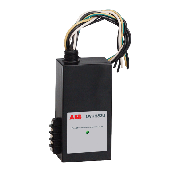
Product features
– Listed to UL 1449 4th Edition for Type 1 and Type 2 SPD
applications.
– Multiple Metal Oxide Varistors (MOVs) with individual and
overcurrent protection.
– LED indicates proper functioning of MOVs
OVRHS3-F1
OVRHS3U
Advertisement

Related Manuals for ABB OVRHS3 Series


Summary of Contents for ABB OVRHS3 Series
- Page 1 Product manual OVRHS3/OVRHS3U series Surge protective devices Installation, operation and maintenance manual OVRHS3 OVRHS3-F1 OVRHS3U Product features – Listed to UL 1449 4th Edition for Type 1 and Type 2 SPD applications. – Multiple Metal Oxide Varistors (MOVs) with individual and overcurrent protection.
- Page 2 Table of Contents Guide to installation and assistance ....3 Important safety instructions ......4 Electrical connections .
-
Page 3: Guide To Installation And Assistance
Guide to installation and assistance Thank you for choosing the ABB WARNING!: OVRHS3/OVRHS3U series Surge THE OVRHS3/OVRHS3U SERIES WARRANTY IS VOIDED if the unit is damaged as a result of improper installation or Protective Device (SPD). We look forward the installer’s failure to verify the following conditions prior to fulfilling your facilitywide surge to installation. -
Page 4: Important Safety Instructions
Important safety instructions Installation 7. Black or brown wires (model dependent) should be connected to either the breaker or the bus of the panel, as long as the short circuit current rating does not exceed Refer to Table 1 to see if an upstream overcurrent protection 65 or 100kAIC (see Table 1 for specific model ratings). - Page 5 Performance data Table 1 Model number SPD type kAIC rating Upstream breaker Wire gauge OVRHS3401201P 1, 2 Not required 14 AWG OVRHS3402301P 14 AWG OVRHS3404801P 14 AWG OVRHS3401202S 1, 2 Not required 14 AWG OVRHS3401203H 14 AWG OVRHS3401203Y 1, 2 Not required 14 AWG OVRHS3402403D...
-
Page 6: Electrical Connections
Electrical connections 1-POLE 2-POLE CIRCUIT BREAKER CIRCUIT BREAKER Xo BOND Xo BOND EARTH GROUND EARTH GROUND Figure 1: 1-phase, 2-wire Figure 2: 2-phase, 3-wire OVRHS3(U)401201P OVRHS3(U)401202S OVRHS3(U)402401P OVRHS3401201P OVRHS3402301P OVRHS3404801P 3-POLE 3-POLE CIRCUIT BREAKER CIRCUIT BREAKER A B C A B C Xo BOND EARTH EARTH... -
Page 7: Connecting Form "C" Dry Contacts
Electrical Service Entry Connecting the remote contacts to an alarm (If option chosen on the OVRHS3U) Protector Protector For “Fail-safe” Form A monitoring, connect the alarm leads to terminals 2 and 3. Terminals 2 and 3 will be closed during normal (Power ON) operation and the protector is functioning properly. - Page 8 We reserve the right to make technical changes to the product and to the information in this document without notice. The agreed conditions at the time of the order shall apply. ABB assumes no responsibility for any errors or omissions that may appear in this document.