Table of Contents
Advertisement
Quick Links
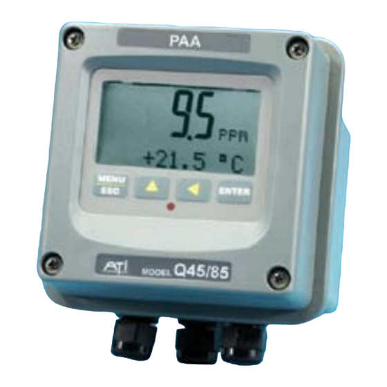
Model Q45/85
2-Wire Peracetic Acid
Home Office
Analytical Technology, Inc.
6 Iron Bridge Drive
Collegeville, PA 19426
Ph:(800) 959-0299
(610) 917-0991
Fax: (610) 917-0992
Email: sales@analyticaltechnology.com
Transmitter
European Office
ATI (UK) Limited
Unit 1 & 2 Gatehead Business Park
Delph New Road, Delph
Saddleworth OL3 5DE
Ph: 0800-018-4020
+ 44 (0) 1457-873-318
Fax: + 44 (0) 1457-874-468
Email:sales@atiuk.com
Advertisement
Table of Contents

Related Manuals for Analytical Technology Q45

Summary of Contents for Analytical Technology Q45
- Page 1 Model Q45/85 2-Wire Peracetic Acid Transmitter Home Office European Office Analytical Technology, Inc. ATI (UK) Limited 6 Iron Bridge Drive Unit 1 & 2 Gatehead Business Park Collegeville, PA 19426 Delph New Road, Delph Saddleworth OL3 5DE Ph:(800) 959-0299 Ph: 0800-018-4020...
- Page 2 PRODUCT WARRANTY Analytical Technology, Inc. (Manufacturer) warrants to the Customer that if any part(s) of the Manufacturer's equipment proves to be defective in materials or workmanship within the earlier of 18 months of the date of shipment or 12 months of the date of start- up, such defective parts will be repaired or replaced free of charge.
-
Page 3: Table Of Contents
Standard System ........5 7.11 PAA Zero Cal ..........48 Features ............. 8 7.12 PAA Span Cal ..........49 Q45/85 System Specifications ....9 Temperature Calibration ......51 Q45H Performance Specifications ...10 pH Calibration..........52 PART 2 – ANALYZER MOUNTING ....11 7.31 Two-Point pH Cal ........52 7.32... - Page 4 YSTEM W AYONET TYLE P ENSOR 3 - S ..............7 IGURE EALED LOWCELL SSY W ONTROL 4 - Q45 E ................... 12 IGURE NCLOSURE IMENSIONS 5 - W ................. 13 IGURE ALL OR IPE MOUNT RACKET 6 - W ..................
-
Page 5: Part 1 - Introduction
5-17 VDC Externally powered unit with two voltage outputs. This manual refers to the Loop-Powered 2-wire transmitter version. In addition to normal chlorine measurement, the Q45/85 is also available with an optional pH input which provides a two-parameter monitoring system. Both PAA and pH are displayed simultaneously, and the PAA value is automatically compensated for pH changes. -
Page 6: Standard System
Part 1 – Introduction Standard System The standard model Q45/85 system includes three main components, the Q45 analyzer, a constant head flow cell, and a PAA sensor. A low-volume flowcell is also available for applications where sample flowrate and pressure can be carefully controlled. -
Page 7: Figure 2 - System W /Bayonet
Q45/85 PAA System Part 1 – Introduction Error! Reference source not found. below shows the same standard flowcell assembly and PAA sensor along with the conventional type pH sensor. A special adapter is required to hold the pH sensor in its proper location in the flowcell inlet chamber. -
Page 8: Figure 3 - Sealed Flowcell
Q45/85 PAA System Part 1 – Introduction Figure 3 - Sealed Flowcell Assy w/Flow Control below shows an installation using a (00-1522) sealed flowcell for the PAA sensor and a (00-1527) sealed flowcell for the pH sensor. This type of installation requires careful flow control. -
Page 9: Features
Q45/85 PAA System Part 1 – Introduction Features · Standard Q45/85 transmitters are fully isolated, loop powered instruments for 2- wire DC applications. · High accuracy, high sensitivity system, measures from 0.01 ppm to 2000 ppm through 4 internal automatic ranges. User ranges of 0-20.00 ppm, 0-200.0 ppm, or 0-2000 ppm. -
Page 10: Q45/85 System Specifications
Q45/85 PAA System Part 1 – Introduction Q45/85 System Specifications Displayed Parameters Main input, 0.01 ppm to 2000 ppm Sensor temperature, -10.0 to 55.0 °C (23 to 131 ºF) Sensor Current, 0.0–999.9 nA, 0.000 to 99.99 uA Loop current, 4.00 to 20.00 mA... -
Page 11: Q45H Performance Specifications
Q45/85 PAA System Part 1 – Introduction Sensor Materials Noryl and Kynar Sensor Cable 25 ft. (7.5 meter) cable with 6-pin plug. Max. Sensor-to-Analyzer 100 feet (30.5 meters), with junction box Distance Optional pH Input 0-14 pH corresponding to approx. 0.3 – 1.5 VDC... -
Page 12: Part 2 - Analyzer Mounting
Part 2 – Analyzer Mounting General All Q45 Series instruments offer maximum mounting flexibility. A bracket is included with each unit that allows mounting to walls or pipes. In all cases, choose a location that is readily accessible for calibrations. Also consider that it may be necessary to utilize a location where solutions can be used during the calibration process. - Page 13 Q45/85 PAA System Part 2– Analyzer Mounting Figure 4 - Q45 Enclosure Dimensions O&M Manual Rev J (8/14)
-
Page 14: Wall Or Pipe Mount
Q45/85 PAA System Part 2– Analyzer Mounting Wall or Pipe Mount A PVC mounting bracket with attachment screws is supplied with each transmitter (see Figure 55 for dimensions). The multi-purpose bracket is attached to the rear of the enclosure using the four flat head screws. -
Page 15: Figure 6 - Wall Mountingd
Q45/85 PAA System Part 2– Analyzer Mounting MENU ENTER Figure 6 - Wall Mounting Diagram MENU ENTER Figure 7 - Pipe Mounting Diagram O&M Manual Rev J (8/14) -
Page 16: Part 3 - Sensor/Flowcell Mounting
Part 3 – Sensor/Flowcell Mounting General Select a location within the maximum sensor cable length for mounting of the sensor flow cell. Constant-Head Flowcell PAA sensors are best used in a constant-head overflow chamber because variations in sample flow rate and pressure can cause unstable readings. When monitoring low concentrations (below 0.5 PPM), this method should always be used. - Page 17 Q45/85 PAA System Part 3 – Sensor/Flowcell Mounting O&M Manual Rev J (8/14)
-
Page 18: Sealed Flowcell
Q45/85 PAA System Part 3 – Sensor/Flowcell Mounting Once mounted, inlet and drain connections must be made. The flow cell contains a 1/8" MNPT inlet connection and a 3/8" MNPT drain connection. Hose barbs for the inlet and drain connections are supplied with the flow cell for use with flexible tubing. -
Page 19: Figure 10 - Sealed P H F
Q45/85 PAA System Part 3 – Sensor/Flowcell Mounting Figure 10 - Sealed pH Flowcell Details O&M Manual Rev J (8/14) -
Page 20: Submersion Mounting
Q45/85 PAA System Part 3 – Sensor/Flowcell Mounting Submersion Mounting Some applications are much easier done using the submersible sensor. This method can sometimes be used where flow is reasonably constant, and hydraulic head does not vary appreciably. PAA sensors can never be used in completely stagnant conditions. -
Page 21: Part 4 - Electrical Installation
Part 4 – Electrical Installation General The Q45 is powered in one of 3 ways, depending on the version purchased. The 2-wire version is a 16-35 VDC powered transmitter. The battery powered unit is supplied with 2-“C” cell batteries. The 5-17 VDC Externally Powered Transmitter is designed for low power operation for solar power applications. -
Page 22: Figure 12 - Loop Powers
Q45/85 PAA System Part 5 – Sensor Assembly Figure 12 - Loop Power Sensor Connection Notes: 1. Voltage between Terminals 12 and 13 MUST be between 16 and 35 VDC. 2. Earth ground into Terminal 15 is HIGHLY recommended. This connection can greatly improve stability in electrically noisy environments. -
Page 23: Load Drive
V/I=R, where V=load drive voltage, I=maximum loop current (in Amperes), and R=maximum resistance load (in Ohms). To find the load drive voltage of the two-wire Q45, subtract 16 VDC from the actual power supply voltage being used (the 16 VDC represents insertion loss). -
Page 24: Sensor Wiring
Part 5 – Sensor Assembly Sensor Wiring The sensor cable can be quickly connected to the Q45 terminal strip by matching the wire colors on the cable to the color designations on the label in the monitor. Note that some submersible sensors have a brown wire instead of an orange wire. -
Page 25: Junction Box Connection
Q45/85 PAA System Part 5 – Sensor Assembly Junction Box Connection For installations where the sensor is to be located more than 25 feet from the monitor (max. 100 feet), a junction box must be used. The junction box is shown in Figure 14, and is supplied with a ½"... -
Page 26: Optional Ph Sensor Input
Remove the jumpers if a pH sensor is added. Two types of pH sensors are available for connection to the Q45/85 monitor. A battery powered sensor with internal preamp, #07-0096, provides an amplified signal of 0.3 –... - Page 27 Q45/85 PAA System Part 5 – Sensor Assembly * Note: pH compensation signal may be supplied from a separate isolated voltage input of 0.3-1.5 VDC (75 Ohm resistance across a 4-20 output) O&M Manual Rev J (8/14)
-
Page 28: Figure 16 - Optional P H S
Q45/85 PAA System Part 5 – Sensor Assembly Figure 16 - Optional pH Sensor Connection w/Junction Box O&M Manual Rev J (8/14) -
Page 29: Part 5 - Sensor Assembly
Part 5 – Sensor Assembly PAA Sensor Preparation The PAA sensor supplied with the Q45 is shipped dry. It will not operate until it is prepared by adding electrolyte and a membrane. Preparation of the sensor for operation must be done carefully. The procedure should be done by a qualified technician, and it should only be done when the system is ready for operation. -
Page 30: Figure 18 - Submersible Paa S
Q45/85 PAA System Part 5 – Sensor Assembly Submersible PAA sensors are made up of two separate parts, a submersion holder that also contains the temperature compensating element and a sensing module. The sensing module screws into the holder, with an o-ring providing a water tight connection. -
Page 31: Optional Ph Sensor
Optional pH Sensor An optional pH battery powered sensor is available for use with the Q45 system that outputs a nominal signal of 0.3-1.5 VDC proportional to pH over a range of 0-14 pH units. The Q22P is also available and outputs a standard 4-20 mA analog signal. -
Page 32: Part 6 - Configuration
Part 6 – Configuration User Interface The user interface for the Q45 Series instrument consists of a custom display and a membrane keypad. All functions are accessed from this user interface (no internal jumpers, pots, etc.). RELAY 4-DIGIT INDICATOR MAIN DISPLAY... -
Page 33: Keys
The manual will refer to this key as either MENU or ESC, depending upon its particular function. In the battery- powered version of the Q45, this is also the ON button. To scroll through individual list or display items and to (arrow) change number values. - Page 34 Q45/85 PAA System Part 6 – Configuration Lower Line During normal operation, the lower line of the display indicates user-selected secondary measurements that the system is making. This also includes calibration data from the last calibration sequence and the transmitter model number and software version.
-
Page 35: Software
Q45/85 PAA System Part 6 – Configuration Software The software of the Q45 is organized in an easy to follow menu-based system. All user settings are organized under five menu sections: Measure, Calibration [CAL], Configuration [CONFIG], Control [CONTROL] and Diagnostics [DIAG]. - Page 36 Q45/85 PAA System Part 6 – Configuration To select a list item for modification, first select the proper menu with the MENU key. Scroll to the list item with the UP arrow key and then press the ENTER key. This tells the system that the user wishes to perform a change on that item. For...
-
Page 37: Figure 20 - Software Map
Q45/85 PAA System Part 6 – Configuration Start MENU MENU MENU MENU MENU MENU MEASURE CONFIG CONTROL DIAG SECTIONS (display only) ENTER ENTER ENTER ENTER Temperature Entry Lock Cal PAA *PID 0% Set Hold Set Delay ** Cal pH *PID 100%... -
Page 38: Measure Menu [Measure]
Q45/85 PAA System Part 6 – Configuration 6.22 Measure Menu [MEASURE] The default menu for the system is the display-only menu MEASURE. This menu is a display-only measurement menu, and has no changeable list items. When left alone, the instrument will automatically return to this menu after approximately 30 minutes. -
Page 39: Calibration Menu [Cal]
Q45/85 PAA System Part 6 – Configuration 7.56 pH Measured pH value on AUX input (if enabled.) 5.00 mV pH sensor mV output (if enabled) Slope = 100% pH sensor slope response vs. ideal calibration. This value will update after each calibration. As the pH sensor ages, the slope reading will decay. -
Page 40: Configuration Menu [Config]
Q45/85 PAA System Part 6 – Configuration Set Range This function allows the user to set the display range of the transmitter to a specific application. Once set, all output functions use this display range to establish configuration settings. Press ENTER to initiate user entry mode, and the value will flash. - Page 41 Q45/85 PAA System Part 6 – Configuration Contrast This function sets the contrast level for the display. The custom display is designed with a wide temperature range, Super-Twist Nematic (STN) fluid. The STN display provides the highest possible contrast and widest viewing angle under all conditions.
- Page 42 Q45/85 PAA System Part 6 – Configuration pH Input Enables the auxiliary pH input on the instrument. Once enabled, an optional pH sensor can be added to the instrument to provide for additional monitoring of pH (dual instrument, PAA + pH output.) Once enabled, the pH input value is displayed on the lower line of the MEASURE screens.
-
Page 43: Figure 15 - O
Q45/85 PAA System Part 6 – Configuration Table 1 Table 2 4.00 pH 7.00 pH 10.00 pH 4.00 pH 7.00 pH 9.18 pH ºC °C °C ºC °C °C 4.00 7.10 10.27 4.00 7.10 9.46 3.99 7.06 10.15 3.99 7.06 9.33... -
Page 44: Control Menu [Control]
Q45/85 PAA System Part 6 – Configuration 6.25 Control Menu [CONTROL] The Control Menu contains all of the output control user settings: Set 4 mA These functions set the main 4 and 20 mA current loop Set 20 mA output points for the transmitter. The units displayed depend... - Page 45 Q45/85 PAA System Part 6 – Configuration PID Setpnt The measured value which the controller is attempting to [Iout1=PID] maintain by adjusting output value. It is the nature of the PID controller that it never actually gets to the exact value and stops.
-
Page 46: Diagnostics Menu [Diag]
Q45/85 PAA System Part 6 – Configuration 6.26 Diagnostics Menu [DIAG] The diagnostics menu contains all of the user settings that are specific to the system diagnostic functions, as well as functions that aid in troubleshooting application problems. Set Hold... - Page 47 Q45/85 PAA System Part 6 – Configuration Faults are not stored; therefore, they are immediately removed if power is cycled. If the problem causing the faults still exists, however, faults will be displayed again after power is re-applied and a period of time elapses during which the diagnostic system re-detects them.
- Page 48 Q45/85 PAA System Part 6 – Configuration The starting display value will be the last read value of the input. The output will be under control of the SIM screen until the ESC key is pressed. Note: If the HOLD function is engaged before the Sim Output function is engaged, the simulated output will remain the same even when the ESC key is pressed.
-
Page 49: Part 7 - Calibration
Part 7 – Calibration PAA Calibration Once power is applied, the sensor must be given time to stabilize. This is best done by following the zeroing procedure below. Establishing a stable zero is critical to the proper operation of the monitor. A complete calibration will include zeroing and spanning the sensor. -
Page 50: Paa Span Cal
Q45/85 PAA System Part 7 – Calibration The system now begins acquiring data for the sensor zero calibration value. As data is gathered, the units for sensor current in nanoamps (nA) and temperature may flash. Flashing units indicate that this parameter is unstable. - Page 51 Q45/85 PAA System Part 7 – Calibration 2. Turn on the inlet water flow to the flow cell and adjust the inlet flow rate so that water is overflowing from the inlet chamber. The best performance will be obtained when some water is always overflowing. This maintains constant flow and pressure on the sensor at all times.
-
Page 52: Temperature Calibration
Q45/85 PAA System Part 7 – Calibration Temperature Calibration The temperature calibration sequence is essentially a 1-point offset calibration that allows adjustments of approximately ±5 °C. The sensor temperature may be calibrated on line, or the sensor can be removed from the process and placed into a known solution temperature reference. -
Page 53: Ph Calibration
Q45/85 PAA System Part 7 – Calibration pH Calibration The pH calibration menus will not be seen unless the optional pH sensor input is turned ON and a special pH sensor is connected to the input of the instrument. See Section 6.24 Configuration Menu [CONFIG] for more details. -
Page 54: One-Point Ph Cal
Q45/85 PAA System Part 7 – Calibration Scroll to the next menu item by pressing the UP arrow key once. The menu item Cal pH buf1 will be displayed. 6. Press the ENTER key. The display will begin to flash. Using the UP and LEFT arrow keys, adjust the displayed number to the known value of the pH buffer. - Page 55 Q45/85 PAA System Part 7 – Calibration Scroll to the next menu item by pressing the UP arrow key once. The menu item Cal pH buf1 will be displayed. 5. Press the ENTER key. The display will begin to flash. Using the UP and LEFT arrow keys, adjust the displayed number to the known value of the pH buffer.
-
Page 56: Part 8 - Pid Controller Details
Part 8 – PID Controller Details PID Description PID control, like many other control schemes, are used in chemical control to improve the efficiency of chemical addition or control. By properly tuning the control loop that controls chemical addition, only the amount of chemical that is truly required is added to the system, saving money. - Page 57 Q45/85 PAA System Part 8 – PID Controller Details é ù ò output ê ë ú û Where: output = controller output proportional gain integral gain derivative gain time e(t) = controller error (e=measured variable – setpoint) Figure 22 - Q45H ISA (Ideal) Equation The most notable feature of the algorithm is the fact the proportional gain term affects all components directly (unlike some other algorithms - like the “series”...
-
Page 58: Classical Pid Tuning
The P value is then reduced to ½ of the oscillatory value, and the I term is increased to give the desired response. This can be done with the Q45 controller, with the exception that the I term should start no lower than 1.0. -
Page 59: Manual Pid Override Control
Part 8 – PID Controller Details Manual PID Override Control The Q45 PID output function allows the user to take manual control of the PID control signal. This is often useful when starting up a control loop, or in the event that you wish to bump the system manually to measure system response time. - Page 60 Q45/85 PAA System Part 8 – PID Controller Details The easiest processes to control with closed-loop schemes are generally linear, and symmetrical, in nature. For example, controlling level in tank where the opening of valve for a fixed period of time corresponds linearly to the amount that flows into a tank.
-
Page 61: Part 9 - System Maintenance
Part 9 – System Maintenance General The Q45/85 PAA System will generally provide unattended operation over long periods of time. With proper care, the system should continue to provide measurements indefinitely. For reliable operation, maintenance on the system must be done on a regular schedule. Keep in mind that preventive maintenance on a regular schedule is much less troublesome than emergency maintenance that always seems to come at the wrong time. -
Page 62: Sensor Acid Cleaning
Q45/85 PAA System Part 10– Troubleshooting Even if no buildup is apparent on the membrane, it should be changed on a regular schedule. The recommended membrane change interval is every 3 months. For high purity water applications, this can probably be extended if desired, but a more frequent changing interval is a small price to pay for avoiding membrane failure at the wrong time. -
Page 63: Q22P Sensor Cleaning
Q45/85 PAA System Part 10– Troubleshooting 3. Fill the beaker with distilled water to the level sufficient to submerge both the tip and the silver coil. Do not allow the connector at the back of the sensor to be submerged. Allow the electrodes to soak in distilled water for 30 minutes. -
Page 64: Replacing The Saltbridge And Reference Buffer Solution
Q45/85 PAA System Part 10– Troubleshooting Replacing the Saltbridge and Reference Buffer Solution 1. Hold the sensor with the process electrode pointing up. Place a cloth or towel around the saltbridge. Turn the saltbridge counterclockwise (by hand) to loosen and remove the saltbridge. Do NOT use pliers. -
Page 65: Flow Cell Maintenance
Q45/85 PAA System Part 10– Troubleshooting Flow Cell Maintenance The maintenance on the flow cell is simple cleaning. The flow cell is clear to make examination of the condition of the sensor easier without interfering with operations. The flow cell may be cleaned by wiping or by washing with detergents or dilute acids. -
Page 66: Part 10 - Troubleshooting
If low voltage signal cables must come near power wiring, cross them at 90° to minimize coupling. 5. If rigid conduit has been run directly to the Q45 enclosure, check for signs that moisture has followed conduit into the enclosure. -
Page 67: Analyzer Tests
PAA reading should display approximately 0 ppm. 10.4 Display Messages The Q45 Series instruments provide a number of diagnostic messages which indicate problems during normal operation and calibration. These messages appear as prompts on the secondary line of the display or as items on the Fault List. - Page 68 Q45/85 PAA System Part 10– Troubleshooting MESSAGE DESCRIPTION POSSIBLE CORRECTION Max is 200 Entry failed, maximum user value allowed is 200. Reduce value to ≤ Min is 200 Entry failed, minimum value allowed is 200. ≥ Increase value to Cal Unstable Calibration...
- Page 69 Q45/85 PAA System Part 10– Troubleshooting MESSAGE DESCRIPTION POSSIBLE CORRECTION PAA Cal Fail Failure of PAA calibration. FAIL icon will Clean sensor redo zero and span calibration. not extinguish until successful calibration If still failure, sensor slope may be less than has been performed, or 30 minutes passes 25% or greater than 250%.
-
Page 70: Sensor Tests
Q45/85 PAA System Part 10– Troubleshooting 10.5 Sensor Tests 1. Check the membrane condition. A membrane that is not stretched smoothly across the tip of the sensor will cause unstable measurements. If necessary, change membrane and electrolyte. 2. Residual PAA sensors can be tested with a digital voltmeter (DVM) to determine if a major sensor problem exists. -
Page 71: Figure 26 - P T
Q45/85 PAA System Part 10– Troubleshooting Temperature Resistance °C 100.0 101.9 103.9 105.8 107.8 109.7 111.7 113.6 115.5 117.5 119.4 Figure 26 - Pt100 RTD Table If you suspect that water has gotten into a cable connection on a flow type sensor or into the plug connection of a submersible sensor, disconnect the cable and allow the parts of the sensor to sit in a warm place for 24 hours. -
Page 72: Spare Parts
Spare Parts Part No. Description Spare Electronics 07-0169 2-Wire monitor electronics assembly 03-0386 Q45H-85 PAA Front Lid Assy Spare Sensors 00-1620 PAA sensor, flow type 07-0096 Q22P pH Sensor with connector (not waterproof) 63-0101 25’ Combination pH Sensor (w/Solution Ground) Spare Sensor Components 02-0018 Sensing element body, (for #00-1620)
Need help?
Do you have a question about the Q45 and is the answer not in the manual?
Questions and answers