Table of Contents
Advertisement
Quick Links
Advertisement
Table of Contents

Summary of Contents for Creotech KLMKBM-01
- Page 1 KLMKBM-01 Bluetooth module instructions Ble mesh...
- Page 2 Version update instructions Date Content Version New document 2021-05-08 V1.0.0...
-
Page 3: Table Of Contents
Catalogue 1 Product description ......................... 4 2 Performance characteristics ....................4 2.1 main feature ........................4 3 Module interface ........................4 3.1 Size package ........................4 3.2 Pin definition ....................... 5 4 Electrical parameters ......................6 4.1 Absolute electrical parameters ................6 4.2 Working conditions ....................... -
Page 4: Product Description
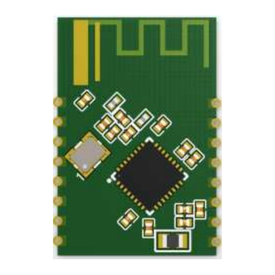
The KLMKBM-01 Bluetooth module has 2 rows of pins, with a pitch of 2mm. KLMKBM-01 Bluetooth module size: 16 ± 0.35 mm (W) × 24 ± 0.35mm (L) × 2.8 ± 0.15mm(H), and the PCB thickness is 0.8mm±0.1 mm.The package is shown in Figure... -
Page 5: Pin Definition
Figure 3.1 Schematic diagram of KLMKBM-01 Bluetooth module 3.2 Pin definition The interface pin definition is shown in Table 3.2: Table 3.2 KLMKBM-01 Bluetooth module interface pinout description Symbol Features Types Hardware reset pin (active low), corresponding to RESETB of IC. -
Page 6: Electrical Parameters
GPIO port, can be used as LED drive PWM output, default corresponding to red light GPIO port, can be used as LED driver PWM output, default corresponding to cold white light Serial port receiving pin UART RX Serial port sending pin UART TX Note: P stands for power supply pin, I/O stands for input and output pin, AI stands for analog input. -
Page 7: Power Consumption In Working Mode
4.3 Power consumption in working mode Table 4.3 Power consumption during TX continuous transmission Condition Symbol Typical Unit Continuous transmission, 10.5dBm output power Continuous reception In Mesh network working state Deep sleep mode (reserved deepsleep1 16KBRAM) Deep sleep mode (no RAM deepsleep2 reserved) 5 RF parameters... -
Page 8: Module Basic Instructions
Co-channel interference suppression 6 Module basic instructions KLMKBM-01 module recommends that users can access the network through the APP-"zhihui connect" developed by our company configuration. Two bulbs are needed for control, and our module needs to be soldered to the corresponding lamp board. - Page 9 6.2 Group control Enter the created group to control the devices assigned to the group at the same time. 6.3 Single light control After the added device enters the device control page, you can perform other operation controls such as switching/dimming of a single light. 6.4 Other settings Timing/countdown can be set, device OTA and bulb can be deleted from the network.
-
Page 11: Appendix Statement
-- Consult the dealer or an experienced radio/TV technician for help. FCC ID: 2AZTV-KLMKBM-01 Warning: Changes or modifications to this unit not expressly approved by the part responsible for compliance could void the user’s authority to... - Page 12 In these circumstances, the OEM integrator will be responsible for re-evaluating the end product (including the transmitter) and obtaining a separate FCC authorization. End product labeling: The final end product must be labeled in a visible area with the following: “Contains Transmitter Module FCC ID: 2AZTV-KLMKBM-01”.
- Page 13 Information that must be placed in the end user manual: The OEM integrator has to be aware not to provide information to the end user regarding how to install or remove this RF module in the user's manual of the end product which integrates this module.
- Page 14 (for example, digital device emissions, PC peripheral requirements, etc.). 2.8 Label and compliance information Host product manufacturers need to provide a physical or e-label stating “Contains FCC ID: 2AZTV- KLMKBM-01”with their finished product.
- Page 15 2.9 Information on test modes and additional testing requirements Operation Frequency: 2402~2480MHz Number of Channel: 40 Modulation: GFSK Host manufacturer must perfom test of radiated & conducted emission and spurious emission, etc according to the actual test modes for a stand-alone modular transmitter in a host, as well as for multiple simultaneously transmitting modules or other transmitters in a host product.
- Page 16 FCC STATEMENT : This device complies with Part 15 of the FCC Rules. Operation is subject to the following two conditions: (1) This device may not cause harmful interference, and (2) This device must accept any interference received, including interference that may cause undesired operation.
- Page 17 Labels Host Device must contain the following label on the outside of the unit: Contains FCC ID:2AZTV-KLMKBM-01 Installation Guidance The final host / module combination may also need to be evaluated against the FCC Part 15B criteria for unintentional radiators in order to be properly authorized for operation as a Part 15 digital device.
Need help?
Do you have a question about the KLMKBM-01 and is the answer not in the manual?
Questions and answers