
Related Manuals for Hubbell inSIGHT HBLGW0400EEUS2

Summary of Contents for Hubbell inSIGHT HBLGW0400EEUS2
- Page 1 Data Monitoring Ethernet Gateway User’s Manual Version 1.1 Wiring Device – Kellems Hubbell Incorporated (Delaware) Shelton, CT 06484 1-800-288-6000 www.hubbell-wiring.com PD2864 6/19...
-
Page 2: Table Of Contents
Power ............................... 12 Gateway Web Console ......................... 13 Status ............................... 13 Monitoring Data ..........................14 Update images to Hubbell gages ............Error! Bookmark not defined. Data Sources ............................ 15 Data Destinations ..........................17 System ............................. 18 Firmware Upgrades ..........................27 SNMP Implementation .......................... - Page 3 Hubbell Ethernet Gateway V1.1 User’s Manual Modbus Device IDs .......................... 52 Accessing and Verifying Modbus Readings Using the Gateway Console ........54 Exporting Modbus Readings ......................55 MTConnect Implementation ......................... 56 EthernetIP Implementation ........................57 Technical Specifications ........................59 Regulatory Information and Labels ....................... 60 Regulatory Information ........................
-
Page 4: Ethernet Gateway Overview
Hubbell Ethernet Gateway V1.1 User’s Manual Ethernet Gateway Overview The Ethernet Gateway is a key component of the Hubbell system architecture. It provides an interface between the wireless monitoring devices and the monitoring application. The Gateway automatically detects any new monitoring devices, seamlessly adding them to the network. -
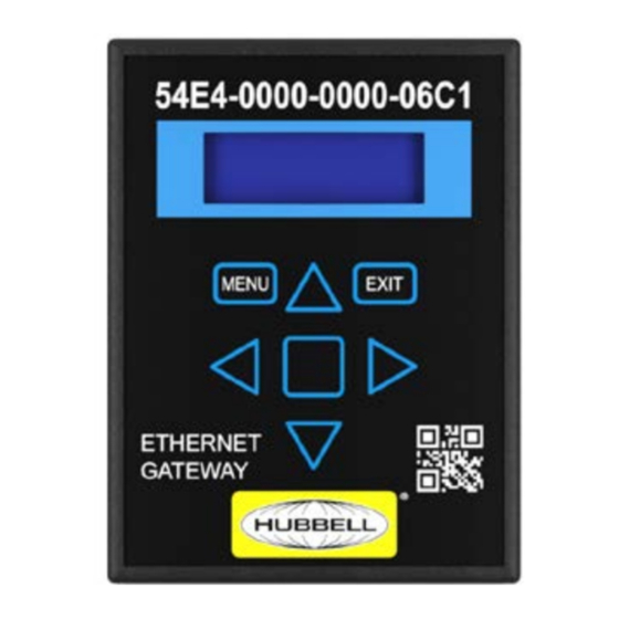
Page 5: Network Configuration
Network Configuration Installing the Ethernet Gateway Each location in which Smart Power Cables are deployed must have one or more Hubbell Ethernet Gateways to gather data from the Smart Power Cables. Refer to Hubbell’s Ethernet Gateway User’s Manual or Quick Start Guide for more information. - Page 6 Hubbell Ethernet Gateway V1.1 User’s Manual Gateway LCD menu The network status menu will display any configured network parameters. Version: Gateway's firmware version IP Address: Programmed IP address MAC Address: Applicable MAC address System Reboot: Reboots the Gateway Uptime: Total time since the Gateway was last energized Turning DHCP on/off using the local LCD Menu The Gateway is provided with DHCP "on"...
-
Page 7: Configuring Using The Gateway Web Console
Hubbell Ethernet Gateway V1.1 User’s Manual Configuring using the Gateway Web Console Once an IP address is assigned to the Gateway either manually or via DHCP, you can access the Gateway console using a standard web browser and entering the IP address of the Gateway. - Page 8 Hubbell Ethernet Gateway V1.1 User’s Manual To access the network settings, click the "System" tab on the left. In the System tab sub menu, click the “Networking” tab. If DHCP is “on” you will not be able to access any network setting until it is switched off under the Network Interface section.
- Page 9 Hubbell Ethernet Gateway V1.1 User’s Manual If using DNS (Domain Name Servers), input the server address under the Domain Name Server section. In order for the Gateway to have a proper time reference, a NTP server address is needed in the Time Synchronization Section.
- Page 10 7. For local EMX implementation, enter the IP address of the server. 8. Before you can access your data via EMX make sure your Hubbell representative has set up an EMX account. See the support section for additional details.
-
Page 11: Physical Installation
• Redundant Gateways are advised for any critical environment • One Gateway can support up to 150 Hubbell monitoring devices; additional Gateways will improve polling speeds • If you are placing multiple Gateways for better coverage or redundancy, try to space them approximately evenly throughout the facility as they will automatically balance network traffic •... -
Page 12: Mounting Bracket
Hubbell Ethernet Gateway V1.1 User’s Manual Never place Gateways inside metallic cabinets. Mounting Bracket • The Gateway attaches to the mounting bracket using the DIN rail clip which snaps onto the receiver clip on the back of the Gateway •... -
Page 13: Power
Power The Ethernet Gateway uses a standard 5V DC power supply with a 5.5 x 2.1 x 11mm positive-on- center power jack. The following power supply options are available from Hubbell: • Universal 100-240V wall-plug power adapters with a full set of international plugs, including C13 connectors for data center installations •... -
Page 14: Gateway Web Console
Hubbell Ethernet Gateway V1.1 User’s Manual Gateway Web Console The Console is accessed by entering the IP address of the Gateway into a standard web browser. Web Console contents Status - provides a general overview of all critical Gateway functions as well as links to key sections... -
Page 15: Monitoring Data
Hubbell Ethernet Gateway V1.1 User’s Manual (4) Licensed Features: Indicates which features are licensed for use with this Gateway. (5) Data Sources: Indicates from where the Gateway is acquiring data. This can be via wireless monitoring nodes or through other Peer Gateways. -
Page 16: Data Sources
Hubbell Ethernet Gateway V1.1 User’s Manual Data Sources Data Sources indicate from where the Gateway is acquiring its data. This can originate from wireless nodes connected to the Gateway or from peered Gateways which are connected to the Gateway via the Ethernet network. - Page 17 Hubbell Ethernet Gateway V1.1 User’s Manual Peer Gateways Gateways can be peered (connected) with other Gateways over the network. This allows for retrieving data from multiple Gateways by polling a single Gateway. The peered Gateways do not have to be in similar locations as long as they are permitted to communicate with each other over the network.
-
Page 18: Data Destinations
Select “Local EMX” in the “Monitoring Data Feed” and “Upgrade and Support Data Feed” sections • Enter the IP address of the local EMX server. Note: Before you can access your data via EMX make sure your Hubbell representative has set up an EMX account. PD2864 6/19... -
Page 19: System
System The following resources are accessible under the "System" menu. Dashboard The Dashboard feature is a diagnostic tool for use by Hubbell and authorized partners. It may not be exposed on all Gateways. Networking The Networking tab allows for the input of network settings. See the... - Page 20 Hubbell Ethernet Gateway V1.1 User’s Manual Authentication Configure your desired method of authenticating user access to the Gateway. Several options exist including "None". PD2864 6/19 Page 19...
- Page 21 Hubbell Gateways and monitors are capable of transmitting on both the 900 MHz and 2.4 GHz bands in the ISM spectrum along with segregated channels within these bandwidths. Depending on geographic region or country there are specific bandwidths required.
- Page 22 Gateway and monitors to an “Isolation Group” (2). Note that both the Gateway and nodes must share the same radio isolation group for successful communication. Modification of radio isolation groups should only be done with guidance from Hubbell. Node Firmware Update The Node Firmware Update feature allows the Gateway to wirelessly broadcast firmware updates to all monitoring nodes communicating with a given Gateway.
- Page 23 Hubbell Ethernet Gateway V1.1 User’s Manual Note that a node firmware update may take a long time. During the uploading process the node will be fully operational using the existing firmware. Once the upload is complete the node will automatically reboot and revive with the newer firmware version. The node may be offline for a very short time during the reboot process.
- Page 24 Hubbell Ethernet Gateway V1.1 User’s Manual To initiate a system update: Select an "Update File” by clicking the “Choose File” button (1). Update files are provided from Hubbell. Click the “Upload” button (2). The system upgrade may take upwards of 30 minutes.
- Page 25 Note that the exchange process may require a reboot in some cases. License Various features of the Gateway will require a separate product license. These licenses can be implemented by uploading the license file provided by Hubbell or an authorized partner. Licensed features include: •...
- Page 26 Logs Logs provide critical operational details relating to the Gateway operation. They are retrieved for debugging purposes and used strictly by Hubbell engineers. To obtain a log file: 1. Select the [Logs] tab from the [System] menu on the right hand task bar.
- Page 27 Hubbell Ethernet Gateway V1.1 User’s Manual PD2864 6/19 Page 26...
-
Page 28: Firmware Upgrades
The Ethernet Gateway Version 4 provides a means of performing firmware upgrades to both itself and to most Hubbell wireless monitoring units. Upgrades are performed via the "System" page of the web console. Detailed instructions can be found in the Web Console - System section. -
Page 29: Snmp Implementation
Hubbell Ethernet Gateway V1.1 User’s Manual SNMP Implementation The following are step-by-step instructions for implementing SNMP using the Ethernet Gateway Version 4. These instructions are intended for SNMP versions 1 and 2. The Version 4 Gateway does support version 3 SNMP. For details on version 3 implementation please contact techserv@hubbell.com. -
Page 30: Accessing The Gateway Console
Hubbell Ethernet Gateway V1.1 User’s Manual Accessing the Gateway Console Make sure your Gateway is configured with an IP address and accessible on your network. The Gateway must be connected to a switch /router on an accessible network. It may not be accessible directly through a PC Ethernet to Gateway connection. For Gateway network... - Page 31 Hubbell Ethernet Gateway V1.1 User’s Manual Downloading the standard MIB file On the Gateway console go to Data Destinations>SNMP on the left menu and then click on the standard MIB file. Downloading the MIB file for use with virtual IP addressing On the Gateway console go to Data Destinations>SNMP>Nodes on the left menu and then click to...
-
Page 32: Accessing Active Oids
Hubbell Ethernet Gateway V1.1 User’s Manual Accessing active OIDs It is possible to download a CSV file that contains only the active data points being received by the Gateway in an SNMP compatible format. This will vary as nodes are added and removed from the system. -
Page 33: Viewing Monitoring Node Readings On The Gateway Console
Hubbell Ethernet Gateway V1.1 User’s Manual Viewing monitoring node readings on the Gateway Console (1) Confirm that monitoring nodes are active and returning data to the Gateway by selecting the “Monitoring Data” tab; this will display all connected nodes (2) Click on the “readings” icon to expose the real time readings for a specific monitoring node... -
Page 34: Uploading An Snmp License To The Gateway
A reboot of the device will be required to make the license effective. The reboot tab can be found under the “System” menu. In the event that SNMP is not a licensed feature you will need to obtain a license from Hubbell techserv@hubbell.com. -
Page 35: Enabling And Configuring The Snmp Agent
Hubbell Ethernet Gateway V1.1 User’s Manual Enabling and configuring the SNMP Agent (1) Click on the SNMP tab under the Data Destinations tab (2) Make sure SNMP is enabled in the check box (3) Select the correct SNMP version. This guide is for SNMP V1 and V2; for SNMP V3... -
Page 36: Using The Ireasoning Mib Browser
Hubbell Ethernet Gateway V1.1 User’s Manual Using the iReasoning MIB browser Loading general MIB files on to the iReasoning browser (1) Load the MIB for “General SNMP management” using the [Load MIBs] function under the [FILE] menu (2) This is the “SNMPv2-MIB” file if using SNMP V2. For older SNMP versions use the appropriate MIB file supplied in the MIB directory. - Page 37 Hubbell Ethernet Gateway V1.1 User’s Manual Download these MIB files. Accessing MIB files on the iReasoning Browser The SNMP management MIB can be found under the “mgmt.” file of the MIB tree The Gateway MIB file can be found under the “eg4” directory under the “private” directory The monitoring nodes MIB file can be found under the “monitoringNode”...
- Page 38 (1) Check the system description by clicking on the the “SysDescr” file on the MIB tree mgmt.>mib- 2> SysDescr (2) Right click on the sysDescr file and and select “Get” from the pop up menu (3) The right hand menu should now display “Hubbell EG4 Ethernet Gateway” PD2864 6/19...
- Page 39 Hubbell Ethernet Gateway V1.1 User’s Manual Performing an SNMP “Walk” to confirm data flow (1) Click “Walk” on the Operations bar and then click “Go”; a table will be generated returning all MIBs Note that Windows firewall may have to be turned “off” for proper communications (2) Node “GUIDs”...
- Page 40 Hubbell Ethernet Gateway V1.1 User’s Manual Node Tables / Node Map (1) After performing a “TableView” on “Nodes Table” by selecting the “nodesTable” file, right click and select table view, it will reveal a listing of all nodes associated with the Gateway (2) Node “GUIDs”...
-
Page 41: Virtual Ip Addressing / Assigning Virtual Ips To Monitoring Nodes
Interpreting Readings Data from Table View (1) The 16 digit node ID (GUID) that identifies each Hubbell device (node) is encoded within the OID Clicking on a reading will allow you to associate it with a specific node ID via the OID Any reading OID will always correspond to a specific channel for specific node (ie. - Page 42 Hubbell Ethernet Gateway V1.1 User’s Manual Assigning Virtual IPs to monitoring nodes To apply a Virtual IP address to a specific node open the Gateway Console and select “SNMP” under the “Data Destinations” menu, then select the “Nodes” menu. This will expose all of the nodes for the Gateway (1) Click on the “+”...
- Page 43 Hubbell Ethernet Gateway V1.1 User’s Manual Viewing nodes by Virtual IP address on Gateway Console (1) Each node will now have a VIP (virtual IP) as well as 16 digit GUID (2) These can be found on the “Monitoring Data” tab of the Gateway Console or the “Node” tab under the “SNMP”...
- Page 44 Hubbell Ethernet Gateway V1.1 User’s Manual (1) and (2) Note that after a new IP address is entered it may be necessary to click on the “Advanced” tab and re-enter the properties of the SNMP agent for each unique IP address.
- Page 45 Hubbell Ethernet Gateway V1.1 User’s Manual Readings Definitions mnChannel ID: Identical for all like monitoring devices mnChannel Name: Describes the function of the channel, i.e., Energy for phase A mnValue: Measurement value for the channel mnUnits: Units of measurement, i.e., Watt hours...
-
Page 46: Modbus Tcp/Ip Implementation
Peering Gateways and Using a Master Gateway Hubbell Gateways can be deployed in a master / peer relationship. In this approach, the master gateway gathers data from all of its peers. This makes it easier for monitoring applications to access data as the monitoring application only needs to communicate with the master gateway. -
Page 47: Enabling Modbus Output
Hubbell Ethernet Gateway V1.1 User’s Manual Enabling Modbus Output To enable Modbus output, access the Gateway Console: 1. Make sure your Gateway is configured with an IP address and accessible on your network. 2. The Gateway must be connected to a switch /router on an accessible network. It may not be accessible directly through a PC Ethernet to Gateway connection in all cases. -
Page 48: Enabling And Configuring The Modbus Driver
Hubbell Ethernet Gateway V1.1 User’s Manual Enabling and Configuring the Modbus Driver (1) To enable the Modbus driver, select Modbus tab under the Data Destinations menu in the Gateway Console (2) Make sure that the “Enabled” check box (2) is checked (3) Enter the port number to be used. -
Page 49: Viewing And Verifying Monitoring Data Using The Gateway Console
Hubbell Ethernet Gateway V1.1 User’s Manual Viewing and Verifying Monitoring Data using the Gateway Console (1) To view data for monitoring nodes associated with the Gateway and confirm operation of specific nodes select the “Monitoring Data” tab (1) on the Gateway Console. - Page 50 Hubbell Ethernet Gateway V1.1 User’s Manual Depending on your Gateway, register maps may be pre-loaded on Gateways with firmware versions 1.12.0 or higher and will appear under the Modbus Register Maps table. There are three main register map sets: •...
-
Page 51: Manually Assigning Registers And Register Maps
Hubbell Ethernet Gateway V1.1 User’s Manual Viewing Register Maps (1) Once a register map is loaded or populated it can be accessed in “Register Maps” under the Data Destinations > Modbus menu (2) Each register has a status column to indicate the validity of the register; if the register is reading... - Page 52 Hubbell Ethernet Gateway V1.1 User’s Manual Creating Registers (1) To access and add registers, select the “Register Maps” menu and highlight the specified register (2) Click on the “pencil” icon under the Register Maps table; this will expose the registers.
-
Page 53: Modbus Device Ids
In order to accommodate such large numbers of devices and maintain a simple, common register map for each node, the Hubbell Modbus interface uses multiple Modbus slave IDs and, if necessary, register offsets. Automatically assigning different host IDs to each nodes allows each node to have an identical register map. - Page 54 Hubbell Ethernet Gateway V1.1 User’s Manual The gateway Modbus node to slave ID and register offset mapping can be automatically generated and customized if necessary. Note: the "Map all nodes" button will remove all existing Slave ID mappings and re-assign them in the order of Node ID.
-
Page 55: Accessing And Verifying Modbus Readings Using The Gateway Console
Hubbell Ethernet Gateway V1.1 User’s Manual Accessing and Verifying Modbus Readings Using the Gateway Console To access and verify Modbus readings: Select the “Readings” tab under Data Destinations>Modbus>Register Maps>Readings. A table containing all Modbus readings will be displayed allowing for easy verification. -
Page 56: Exporting Modbus Readings
Hubbell Ethernet Gateway V1.1 User’s Manual Exporting Modbus Readings (1) Readings can also be exported by selecting the utility icon and selecting export all readings. The files are exported in .CSV format and can be viewed in a standard spread sheet. -
Page 57: Mtconnect Implementation
Hubbell Ethernet Gateway V1.1 User’s Manual MTConnect Implementation PD2864 6/19 Page 56... -
Page 58: Ethernetip Implementation
Hubbell Ethernet Gateway V1.1 User’s Manual EthernetIP Implementation PD2864 6/19 Page 57... - Page 59 Hubbell Ethernet Gateway V1.1 User’s Manual PD2864 6/19 Page 58...
-
Page 60: Technical Specifications
Hubbell Ethernet Gateway V1.1 User’s Manual Technical Specifications PD2864 6/19 Page 59... -
Page 61: Regulatory Information And Labels
Pursuant to Part 15.21 of the FCC Rules, any changes or modifications to this product not expressly approved by Hubbell LLC might cause harmful interference and void the FCC authorization to operate this product. Pursuant to part 2.1091c of the FCC rules device is categorically excluded from routine RF Exposure regulations. -
Page 62: Regulatory Label
Hubbell Ethernet Gateway V1.1 User’s Manual pas produire de brouillage, et (2) l'utilisateur de l'appareil doit accepter tout brouillage radioélectrique subi, même si le brouillage est susceptible d'en compromettre le fonctionnement.Conformément à la réglementation d'Industrie Canada, le présent émetteur radio peut fonctionner avec une antenne d'un type et d'un gain maximal (ou inférieur) approuvé...
Need help?
Do you have a question about the inSIGHT HBLGW0400EEUS2 and is the answer not in the manual?
Questions and answers