Advertisement
Advertisement
Table of Contents

Summary of Contents for ZIGBEE PC321-Z-TY
- Page 1 PC321-Z-TY Single/3-phase Power Clamp Quick Start Guide...
-
Page 2: Safety Handling
Safety Handling WARNING: Failure to follow these safety notices could result in fire, electric shock, other injuries, or damage to the Power Clamp and other property. Read all the safety notices below before using the Power Clamp. • Avoid high humidity or extreme temperatures. •... -
Page 3: Technical Specifications
Technical Specifications Wireless Connectivity • 2.4GHz IEEE 802.15.4 ZigBee ZigBee Profile • ZigBee 3.0 • Operating frequency: 2.4GHz • External antenna RF Characteristics • Output Power: Up to +20dBm Physical Specifications • 100~240 Vac 50/60 Hz Operating Voltage • ≤ 100W ( Within ±2W ) Calibrated Metering Accuracy •... - Page 4 Welcome PC321-Z-TY Power Clamp helps you monitor the amount of electricity usage in your facility by connecting the clamp on to the power cable. It can also measure Voltage, Current, ActivePower. This guide will provide you with an overview of the product and help you get through the initial setup to installation.
-
Page 5: Get To Know Your Device
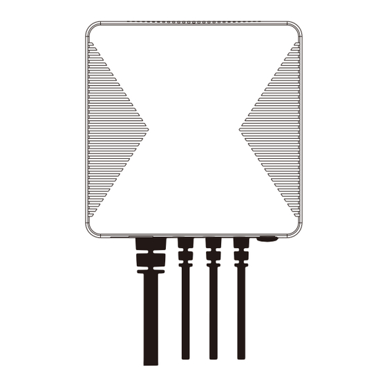
Get to know your device LED indicator External antenna CT: Current Transformer Cable AC Input cable Clamp... - Page 6 (energy data will not be cleared). LED indicator The LED status gives the following information of the power clamp: LED Status What it means Device has not joined a ZigBee network. Green LED No light Device has joined a ZigBee network.
- Page 7 Installaion Important safety information! • The power clamp must be installed and serviced only by a qualified electrical personnel. • Do not touch the terminals of the device during testing. • Turn off all the power supply for this equipment before installing. •...
- Page 8 PC321 Red/L1 Load1 Load2 Load3 Green/L2 Brown/L3 White/N L2/B L1/A L3/C Circuit Breaker Single Phase electricity wiring diagram Follow the steps below: 1. Connect AC Input cable to a socket near the Electrical Box to power on the Power Clamp according to the corresponding phase wiring diagram.
-
Page 9: Configure Network
Configure Network 4.1 To get started, you will need: • A ZigBee Gateway 4.2 Adding to the gateway's network 1. Set your gateway to permit joining (see your gateway's manual). 2. Power on the power clamp and make sure the LED indicator is flashing green. - Page 10 Mounting The Power Clamp has a mounting bracket for mounting purposes. 1. Use the mounting bracket as template to mark the two holes on the wall for installing screws. 2. Screw the mounting bracket onto the wall according to marked location.
Need help?
Do you have a question about the PC321-Z-TY and is the answer not in the manual?
Questions and answers