Table of Contents
Advertisement
Available languages
Available languages
Quick Links
LOV TO ELECTRIC S.P. .
24020 GORLE (BERGAMO) ITALIA
VIA DON E. MAZZA, 12
TEL. 035 4282111
L
E
E-mail info@
ovato
lectric.com
L
E
Web
www.
ovato
lectric.com
W RNING!
– Carefully read the manual before the installation or use.
– This equipment is to be installed by qualified personnel, complying to current standards, to avoid
damages or safety hazards.
– Before any maintenance operation on the device, remove all the voltages from measuring and supply inputs and short-
circuit the CT input terminals.
– The manufacturer cannot be held responsible for electrical safety in case of improper use of the equipment.
– Products illustrated herein are subject to alteration and changes without prior notice. Technical data and descriptions
in the documentation are accurate, to the best of our knowledge, but no liabilities for errors, omissions or
contingencies arising there from are accepted.
– A circuit breaker must be included in the electrical installation of the building. It must be installed close by the
equipment and within easy reach of the operator. It must be marked as the disconnecting device of the equipment:
IEC /EN 61010-1 § 6.11.2.
– Clean the device with a soft dry cloth; do not use abrasives, liquid detergents or solvents.
TTENTION !
– Lire attentivement le manuel avant toute utilisation et installation.
– Ces appareils doivent être installés par un personnel qualifié, conformément aux normes en vigueur en
matière d'installations, afin d'éviter de causer des dommages à des personnes ou choses.
– Avant toute intervention sur l'instrument, mettre les entrées de mesure et d'alimentation hors tension et court-circuiter
les transformateurs de courant.
– Le constructeur n'assume aucune responsabilité quant à la sécurité électrique en cas d'utilisation impropre du
dispositif.
– Les produits décrits dans ce document sont susceptibles d'évoluer ou de subir des modifications à n'importe quel
moment. Les descriptions et caractéristiques techniques du catalogue ne peuvent donc avoir aucune valeur
contractuelle.
– Un interrupteur ou disjoncteur doit être inclus dans l'installation électrique du bâtiment. Celui-ci doit se trouver tout
près de l'appareil et l'opérateur doit pouvoir y accéder facilement. Il doit être marqué comme le dispositif
d'interruption de l'appareil : IEC/ EN 61010-1 § 6.11.2.
– Nettoyer l'appareil avec un chiffon doux, ne pas utiliser de produits abrasifs, détergents liquides ou solvants.
CHTUNG!
– Dieses Handbuch vor Gebrauch und Installation aufmerksam lesen.
– Zur Vermeidung von Personen- und Sachschäden dürfen diese Geräte nur von qualifiziertem
Fachpersonal und unter Befolgung der einschlägigen Vorschriften installiert werden.
– Vor jedem Eingriff am Instrument die Spannungszufuhr zu den Messeingängen trennen und die Stromwandler
kurzschlie en.
– Bei zweckwidrigem Gebrauch der Vorrichtung übernimmt der Hersteller keine Haftung für die elektrische Sicherheit.
– Die in dieser Broschüre beschriebenen Produkte können jederzeit weiterentwickelt und geändert werden. Die im
Katalog enthaltenen Beschreibungen und Daten sind daher unverbindlich und ohne Gewähr.
– In die elektrische Anlage des Gebäudes ist ein Ausschalter oder Trennschalter einzubauen. Dieser muss sich in
unmittelbarer Nähe des Geräts befinden und vom Bediener leicht zugänglich sein. Er muss als Trennvorrichtung für das
Gerät gekennzeichnet sein: IEC/ EN 61010-1 § 6.11.2.
– Das Gerät mit einem weichen Tuch reinigen, keine Scheuermittel, Flüssigreiniger oder Lösungsmittel verwenden.
DVERTENCI
– Leer atentamente el manual antes de instalar y utilizar el regulador.
– Este dispositivo debe ser instalado por personal cualificado conforme a la normativa de instalación
vigente a fin de evitar daños personales o materiales.
– Antes de realizar cualquier operación en el dispositivo, desconectar la corriente de las entradas de alimentación y
medida, y cortocircuitar los transformadores de corriente.
– El fabricante no se responsabilizará de la seguridad eléctrica en caso de que el dispositivo no se utilice de forma
adecuada.
– Los productos descritos en este documento se pueden actualizar o modificar en cualquier momento. Por consiguiente,
las descripciones y los datos técnicos aquí contenidos no tienen valor contractual.
– La instalación eléctrica del edificio debe disponer de un interruptor o disyuntor. Éste debe encontrarse cerca del
dispositivo, en un lugar al que el usuario pueda acceder con facilidad. Además, debe llevar el mismo marcado que el
interruptor del dispositivo (IEC/ EN 61010-1 § 6.11.2).
– Limpiar el dispositivo con un trapo suave; no utilizar productos abrasivos, detergentes líquidos ni disolventes.
UPOZORNĚNÍ
AVERTIZARE!
GB
THREE-PH SE ENERGY METER
WITH CT INSERTION WITH 2 ST TIC OUTPUTS
Instructions manual
DME D305T2
TTENZIONE!
– Leggere attentamente il manuale prima dell'utilizzo e l'installazione.
– Questi apparecchi devono essere installati da personale qualificato, nel rispetto delle vigenti normative
impiantistiche, allo scopo di evitare danni a persone o cose.
– Prima di qualsiasi intervento sullo strumento, togliere tensione dagli ingressi di misura e di alimentazione e
cortocircuitare i trasformatori di corrente.
– Il costruttore non si assume responsabilità in merito alla sicurezza elettrica in caso di utilizzo improprio del dispositivo.
– I prodotti descritti in questo documento sono suscettibili in qualsiasi momento di evoluzioni o di modifiche. Le
descrizioni ed i dati a catalogo non possono pertanto avere alcun valore contrattuale.
– Un interruttore o disgiuntore va compreso nell'impianto elettrico dell'edificio. Esso deve trovarsi in stretta vicinanza
dell'apparecchio ed essere facilmente raggiungibile da parte dell'operatore. Deve essere marchiato come il dispositivo
di interruzione dell'apparecchio: IEC/ EN 61010-1 § 6.11.2.
– Pulire l'apparecchio con panno morbido, non usare prodotti abrasivi, detergenti liquidi o solventi.
UW G !
ПРЕДУПРЕЖДЕНИЕ!
DİKKAT!
G
B
1
Advertisement
Chapters
Table of Contents

Related Manuals for Loavto Electric DME D305T2

Summary of Contents for Loavto Electric DME D305T2
- Page 1 DME D305T2 W RNING! TTENZIONE! – Carefully read the manual before the installation or use. – Leggere attentamente il manuale prima dell’utilizzo e l’installazione. – This equipment is to be installed by qualified personnel, complying to current standards, to avoid –...
-
Page 2: Table Of Contents
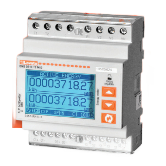
INTRODUCTION The three-phase energy meter with CT insertion, model DME D305T2, has been designed to combine the utmost ease of use with a wide range of advanced functions. Despite the extremely limited dimensions of the modular housing (just 4 modules), the energy meter features the same performance as a high-level device. The backlit LCD display permits a clear and intuitive user interface. The DME D305T2 also features 2 static outputs for pulse generation and a tariff input. -
Page 3: Main Page
– The main page displays the active power currently used in the system, the active power percentage with respect to the rated value for the system and the total active energy meter for the system. – The user can choose the page and sub-page that the DME D305T2 display returns to automatically after a certain time has elapsed without the buttons being pressed. -
Page 4: Table Of Display Pages
TABLE OF DISPLAY PAGES Selection with s and t Selection with N° PAGES SUB-PAGES ACTIVE ENERGY– ACTIVE POWER kWh(TOT) – kW (TOT) – %kW with respect to the rated value IMP. ACTIVE ENERGY METERS kWh+(SYS) PAR TAR-1 TAR-2 kWh+(SYS) TOT EXP. - Page 5 TABLE OF DISPLAY PAGES Selection with s and t Selection with N° PAGES SUB-PAGES ACTIVE POWER UNBALANCE L1-L2, L2-L3, L3-L1 FREQUENCY ASYMMETRY ASY(VLL) ASYMMETRY ASY(VLN) ASYMMETRY ASY(I) PH-PH VOLTAGE HARM. DISTORTION THD-V(L1-L2), THD-V(L2-L3), THD-V(L3-L1) PH-N VOLTAGE HARMONIC DISTORTION THD-V(L1),THD-V(L2),THD-V(L3) CURRENT HARMONIC DISTORTIONE THD-I(L1), THD-I(L2) THD-I(L3) HOUR COUNTER PAR-1...
-
Page 6: Navigating Between The Display Pages
NAVIGATING BETWEEN THE DISPLAY PAGES Phase-to-phase voltages = Instantaneous value = Maximum value = Minimum value = Average value Phase-to-neutral voltages = Instantaneous value = Maximum value = Minimum value = Average value Phase and neutral currents = Instantaneous value = Maximum value = Minimum value = Average value... -
Page 7: Energy Meter Indication
HOUR COUNTER INDICATION – If the hour counter is enabled (see menu P05), the DME D305T2 displays the hour counter page, with the format indicated in the figure: – There is a total hour counter and 4 partial hour counters that can be reset and activated with different sources (see the parameters of the P05 group). -
Page 8: Limit Threshold Status Indication (Limx)
LIMIT THRESHOLD STATUS INDICATION (LIMx) – If the limit thresholds are enabled (see menu P08), the DME D305T2 displays the page, with the corresponding status and the format indicated in the figure: – With limit threshold activated, the word ON flashes, while if it is deactivated the word OFF is constant. If no limit threshold is programmed, dashes are displayed. -
Page 9: Hour Counter Indication
– If no buttons are pressed for two minutes, the setup menu is abandoned automatically and the system returns to the standard display without saving the parameters. – Remember that, solely for the data that can be edited using the buttons, a backup copy can be made in the DME D305T2’s EEPROM. If required, this data can be restored to the working memory. The backup and data restore commands are in the commands menu. - Page 10 M02 – UTILITY Default Range P02.01 Language English English Italiano Francais Espanol Portuguese Deutsch P02.02 High backlight level 0-100 P02.03 Low backlight level 0-50 P02.04 Low backlight delay 5-600 P02.05 Default page return OFF / 10-600 P02.06 Default pag W + kWh VL-L / VL-N …...
- Page 11 M08 – LIMIT THRESHOLDS (LIMn, n=1..4) Default Range P08.n.01 Reference measure OFF- (measures) P08.n.02 Function Max - Min - Min+Max P08.n.03 Upper threshold -9999 - +9999 P08.n.04 Multiplier /100 – x10k P08.n.05 Delay 0.0 – 1000.0 P08.n.06 Lower threshold -9999 - +9999 P08.n.07 Multiplier /100 –...
-
Page 12: Commands Menu
C.16 WIRING TEST Advanced Runs the test to check that the DME D305T2 is connected correctly - See wiring test – Once the required command has been selected, press to execute it. The device will prompt for a confirmation. Pressing again will execute the command. -
Page 13: Terminals Arrangement And Mechanical Dimensions (Mm)
TERMINALS ARRANGEMENT AND MECHANICAL DIMENSIONS [mm] 43.7 O2+ O2-... -
Page 14: Technical Specifications
TECHNICAL SPECIFICATIONS uxiliary supply Measurement and tariff power supply circuit connection Rated voltage Us 220-240V~ L-N / 380-415V~ L-L Type of terminal Screw-type (fixed) The device may operate with or without neutral Number of terminals 4 for supply / measurement Voltage range 187-264V~ L-N / 323-456V~ L-L 2 for tariff selection input... - Page 15 DME D305T2 W RNING! TTENZIONE! – Carefully read the manual before the installation or use. – Leggere attentamente il manuale prima dell’utilizzo e l’installazione. – This equipment is to be installed by qualified personnel, complying to current standards, to avoid –...
-
Page 16: Introduzione
INTRODUZIONE Il contatore di energia trifase a inserzione tramite TA, modello DME D305T2, è stato progettato per unire la massima semplicità di utilizzo con una ampia scelta di funzioni avanzate. Nonostante l’estrema compattezza del contenitore modulare (solo 4 moduli), le prestazioni del contatore di energia sono le stesse di un apparecchio di alto livello. Il display retroilluminato LCD consente una interfaccia utente chiara ed intuitiva. -
Page 17: Visualizzazione Delle Misure
– La pagina principale visualizza la potenza attiva attualmente impegnata nell’impianto, la percentuale della potenza attiva rispetto a quella nominale dell’impianto ed il contatore di energia attiva totale di sistema. – L’utente ha la possibilità di specificare su quale pagina e su quale sotto-pagina il display DME D305T2 deve ritornare automaticamente dopo che è trascorso un tempo senza che siano premuti dei tasti. -
Page 18: Tabella Delle Pagine Del Display
TABELLA DELLE PAGINE DEL DISPLAY Selezione con s e t Selezione con N° PAGINE SOTTOPAGINE ENERGIA ATTIVA – POTENZA ATTIVA kWh(TOT) – kW (TOT) – %kW rispetto alla nominale CONTATORI ENERGIA ATTIVA IMP kWh+(SYS) PAR TAR-1 TAR-2 kWh+(SYS) TOT CONTATORI ENERGIA ATTIVA EXP kWh-(SYS) PAR TAR-1 TAR-2... - Page 19 TABELLA DELLE PAGINE DEL DISPLAY Selezione con s e t Selezione con N° PAGINE SOTTOPAGINE SBILANCIAMENTO POTENZA ATTIVA L1-L2, L2-L3, L3-L1 FREQUENZA ASIMMETRIA ASY(VLL) ASIMMETRIA ASY(VLN) ASIMMETRIA ASY(I) DIST. ARMONICA TENSIONI L-L THD-V(L1-L2), THD-V(L2-L3), THD-V(L3-L1) DIST. ARMONICA TENSIONI L-N THD-V(L1),THD-V(L2),THD-V(L3) DIST.
-
Page 20: Navigazione Fra Le Pagine Del Display
NAVIGAZIONE FRA LE PAGINE DEL DISPLAY Tensioni concatenate = Valore istantaneo = Valore massimo = Valore minimo = Valore medio Tensioni di fase = Valore istantaneo = Valore massimo = Valore minimo = Valore medio Correnti di fase e neutro = Valore istantaneo = Valore massimo = Valore minimo... -
Page 21: Indicazione Contatori Energia
TARIFFE – Per il conteggio dell’energia, il DME D305T2 ha la possibilità di gestire 2 tariffe indipendenti oltre alla totale e alla parziale. – La selezione delle tariffe avviene normalmente tramite l’ingresso digitale, oppure in opzione tramite l’invio di messaggi sul protocollo di comunicazione. -
Page 22: Indicazione Stato Limiti (Limx)
INDICAZIONE STATO LIMITI (LIMx) – Se i limiti sono abilitati (vedere menu P08), il DME D305T2 visualizza la pagina con il relativo stato e con il formato indicato in figura: – Con limite attivato la scritta ON lampeggia, mentre se il limite è disattivato la scritta OFF è fissa. Se un limite non è programmato compaiono i trattini. -
Page 23: Tabella Dei Parametri
– Se non vengono premuti tasti per 2 minuti consecutivi, il menu setup viene abbandonato automaticamente e il sistema torna alla visualizzazione normale senza salvare i parametri. – Rammentiamo che, per i soli dati di setup modificabili da tastiera, è possibile fare una copia di sicurezza (backup) nella memoria eeprom del DME D305T2. Questi stessi dati all’occorrenza possono essere ripristinati (restore) nella memoria di lavoro. - Page 24 M02 – UTILITÁ Default Range P02.01 Lingua English English Italiano Francais Espanol Portuguese Deutsch P02.02 Retroill. Display alta 0-100 P02.03 Retroill. Display bassa 0-50 P02.04 Tempo passaggio a retroilluminazione bassa 5-600 P02.05 Ritorno a pagina di default OFF / 10-600 P02.06 Pagina di default W + kWh...
- Page 25 M08 – SOGLIE LIMITE (LIMn, n=1..4) Default Range P08.n.01 Misura di riferimento OFF- (misure) P08.n.02 Funzione Max - Min - Min+Max P08.n.03 Soglia superiore -9999 - +9999 P08.n.04 Moltiplicatore /100 – x10k P08.n.05 Ritardo 0,0 – 1000,0 P08.n.06 Soglia inferiore -9999 - +9999 P08.n.07 Moltiplicatore /100 –...
-
Page 26: Menu Comandi
Ricarica le impostazioni dalla copia di sicurezza C.16 TEST COLLEGAMENTO Avanzato Esegue il test per verificare la correttezza del collegamento del DME D305T2 - Vedere capitolo Test collegamento – Una volta selezionato il comando desiderato, premere per eseguirlo. Lo strumento chiederà una conferma. Premendo nuovamente il comando verrà... - Page 27 DISPOSIZIONE MORSETTI E DIMENSIONI MECCANICHE [mm] 43.7 O2+ O2-...
- Page 28 CARATTERISTICHE TECNICHE limentazione ausiliaria Connessioni circuito alimentazione / misura e tariffa Tensione nominale Us 220-240V~ L-N / 380-415V~ L-L Tipo di morsetti A vite (fissi) L’apparecchio può funzionare con o senza neutro Numero di morsetti 4 per alimentazione / misura Limiti di funzionamento 187-264V~ L-N / 323-456V~ L-L 2 per ingresso selezione tariffa...