
Related Manuals for NITTOH Power UP-35DX-IN

Summary of Contents for NITTOH Power UP-35DX-IN
- Page 1 ELECTRIC/HYDRAULIC PUMPS UP-35DX-IN(L) Operation and maintenance manual NITTOH ZOHKI CO.,LTD. 102,4-10,2-Chome,Kamezawa,Sumida-ku, Tokyo 130,Japan Telephone.03-3625-6551 Facsimile. 03-3625-6553...
-
Page 2: Table Of Contents
INDEX page 1 Safety information------------------------ 2 Description of components------------- 3 Instructions before use------------------ 4 Operation----------------------------------- 5 Maintenance------------------------------- 6 How to remove the cover--------------- 7 Circuits-------------------------------------- 8 Construction drawings------------------- 11 9 Parts lists----------------------------------- 10 Trouble shooting guide------------------ 11 Warranty------------------------------------... -
Page 3: Safety Information
1 Safety Information Three types of symbols are used in this instruction manual to ensure correct use of the product and to prevent harm to you or others or damage to property. The symbols and their meanings are as follows. Please read the text after understanding the contents carefully. NITTOH ZOHKI is not responsible for any damage or injury resulting from unsafe use of the product, lack of maintenance, or improper application of the system. - Page 4 Precautions for use ⚠ WARNING ■Take safety measures. Use protective equipment, work clothes, safety glasses, etc. to protect yourself when operating hydraulic equipment. ■Pay attention to the allowable pressure of the hydraulic circuit. Always work to ensure that the maximum permissible working pressure of the pump is less than the permissible pressure of other hydraulic equipment connected to it and less than the permissible load.
-
Page 5: Description Of Components
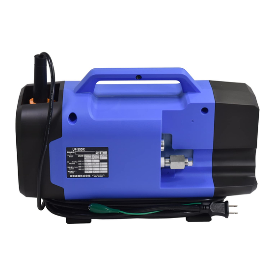
2 Description of components Pump body Back Cover Tank Cover Pump Feet Relief Valve Air Relief Valve Storage Box Oil Feeding Plug Discharge Port 10 Power Cord 11 Operation Cord 12 Fuse 3 Instructions before use 3-1 Please make sure that there is no damage or oil leakage during transportation. ⚠... -
Page 6: Operation
5-1) Hydraulic fluid.) (7) Turn the oil supply plug clockwise to tighten it. Be careful not to damage the O-ring. 4 Operation “UP-35DX-IN(L)” with 2-way normally closed solenoid valve, pressure holding and inching type. - Page 7 5-2 Pressure and piping ⚠ ① Composition of hydraulic equipment system WARNING When combining pumps, high-pressure hoses, cylinders, couplers, valves, etc. to form a hydraulic system, make sure that the maximum working pressure of each device is the same. If a pump with a lower maximum working pressure is used, the maximum working pressure of the system should be adjusted to the lowest one.
- Page 8 5-4 Coupler ① Connection Before connecting the coupler, make sure that there is no dust, sand, etc. attached to the connection part of the coupler. After connecting, pull the high-pressure hose to confirm the connection. ⚠ ② Handling WARNING Do not pressurize the product with the coupler attached to the end of the high-pressure hose without installing the cylinder.
- Page 9 5-6 Carbon brushes ⚠ ① Cautions for use WARNING Always pay attention to the wear of the carbon brushes. When the carbon brush is worn down to 6mm or when the motor has been running for more than 150 hours, replace it with a new one.
-
Page 10: How To Remove The Cover
5-7 How to remove the cover Rubber sheet Fitting bolt M5×10 Hexagon socket ① ⑦ head screw Tank Cover Fitting bolt M5×10 Hexagon socket ② ⑧ head screw Fitting bolt M5×10 Hexagon socket Side cover 1 ③ ⑨ head screw Back Cover Side Cover 2 ④... -
Page 11: Circuits
6 Circuits Hydraulic Circuit Electrical diagram How to change the carbon brush Remove carbon 3.Pull carbon 1. Remove the back cover. brush mounting screw brush and insert a new with a screwdriver. carbon brush. 5. Screw in the carbon brush mounting screw. If there is any 4. -
Page 12: Construction Drawings
7 Construction drawings... -
Page 13: Parts Lists
8 Parts list Part No. Description 2-31 Pushing screw MSWAS12-6 2-32 Driving section suction filter Low pressure Base plate 2-33 suction filter High pressure AC0598A00 Oil seal Returning section TLA1512Z Bearing NW-22B Solenoid Eccentric collar Base block RNAF273013 Bearing Fitting bolt M5×45 Spring Pin Spring washer... -
Page 14: Trouble Shooting Guide
4-11 M3×6 Lock screw Oil feeding plug 4-12 Steel ball P-16 O ring φ6 4-13 Ball pushing Discharge nipple 4-14 O ring TSC-14 Coin filter Tank section O-14 Snap ring Rubber tank 1L 5-10 Pump stay tank side Fixed tank ring 5-11 Fitting bolt M6×10... -
Page 15: Warranty
10 Warranty 10-1) Warranty period For general defects and failures, 365 days from the last day of the month of manufacture. Example: If the pump was purchased on January 1, 2019, the warranty period will be until January 31, 2020. 10-2) Warranty conditions NITTOH products and components are warranted against damage to products and components due to defects in materials and workmanship, with the following exceptions...