Table of Contents
Advertisement
Quick Links
8 Channel Video Receive Unit with 1 Bi-directional Data
Channel and Dual Redundant Operation - includes AMG
NMS Network Management Interface
The AMG3684RN-DR-SF is a rackmount eight channel video receive unit designed to receive up to 8
video signals and transmit & receives one bi-directional data channel to/from a multimode optical fibre
ring with Dual Redundant operation.
The AMG3684RN-DR-SF is designed to plug into an AMG2009 or AMG2015 subrack, which in turn
fits into a 19" rack system. It also includes an AMG Management Interface to allow Management of the
system using the AMG SNMP enabled Management software.
The AMG3684RN-DR-SF is designed to operate with up to eight AMG3613-DR-SF single channel
video insert units. Each receiver will 'drop off' up to eight video channels which are being transmitted
around the fibre ring. The AMG3684RN-DR-SF may also be used with other combinations of single,
dual or four channel video and data insert units.
AMG Systems Ltd. reserves the right to make changes to this
document without notice. The information herein is believed to
be accurate. No responsibility is assumed by AMG for its use.
AMG3684RN-DR-SF
Instruction Manual
Page 1 of 12
AMG3684RN-DR-SF Instruction Sheet
D18232-02.doc
Advertisement
Table of Contents

Related Manuals for AMG AMG3684RN-DR-SF

Summary of Contents for AMG AMG3684RN-DR-SF
- Page 1 The AMG3684RN-DR-SF is designed to plug into an AMG2009 or AMG2015 subrack, which in turn fits into a 19" rack system. It also includes an AMG Management Interface to allow Management of the system using the AMG SNMP enabled Management software.
-
Page 2: Table Of Contents
Removal / replacement from / to the Case ..................11 Safety Maintenance and Repair AMG Systems Ltd. reserves the right to make changes to this Page 2 of 12 AMG3684RN-DR-SF Instruction Sheet document without notice. The information herein is believed to D18232-02.doc... -
Page 3: Introduction
OK and send out the video and data signal on the secondary optical output. This video and data will be transmitted to the next unit around the ring in the opposite direction on the secondary route. AMG Systems Ltd. reserves the right to make changes to this Page 3 of 12 AMG3684RN-DR-SF Instruction Sheet document without notice. -
Page 4: Optical Connections
Optical Connections The AMG3684N-DR-SF or rackmount AMG3684RN-DR-SF is designed to be connected in a ring or point to point system. In a ring system, single, dual and four channel insert units respectively can be combined to make up an 8 channel video transmission system as illustrated below. -
Page 5: Connections
RS232 – switch position – low (furthest from BNC connections) DATA CHANNEL B Data Channel B ........Not Present AMG Systems Ltd. reserves the right to make changes to this Page 5 of 12 AMG3684RN-DR-SF Instruction Sheet document without notice. The information herein is believed to D18232-02.doc... -
Page 6: Data And Audio Channel Configuration
RS485 bus high (+5 volts) and the other arm low (0 volts) using high value resistors within the third party equipment. In order to ensure that the AMG equipment detects a tri-state condition, then these resistors should have a value above 5kΩ. If the third party bias resistors are less the 750Ω... -
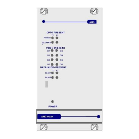
Page 7: Front Panel Indicators
OUT+ logic one (-V) present on OUT+ This represents the data signals being received on the optical fibre AMG Systems Ltd. reserves the right to make changes to this Page 7 of 12 AMG3684RN-DR-SF Instruction Sheet document without notice. -
Page 8: Network Management
Power at the receiver Closed by: Reset The Management Interface The Management Interface is fitted to AMG receivers / transmitters and is signified by a 'N' in the part number AMG Systems Ltd. reserves the right to make changes to this... - Page 9 Each management interface, thus each receiver or transmitter, has an ID number with is identified below the management port. This ID number is used by the AMG Network Management System (NMS) to identify the unit. The physical interface is a 9 way female D-type connector. It supports either RS-232 or RS-485.
-
Page 10: Alarm Output And Reset Operation
On release of the alarm reset, the alarm output will remain in a closed state until the next change of state to the AMG transmit unit connected to the receiver. The alarm output may not register a change of state which happens within 5 seconds of release of the alarm reset. -
Page 11: Physical Information
There are no user serviceable parts within AMG products. See unit data sheet for full specification. In case of problem or failure, please call your local support centre or contact: AMG Systems Ltd. at 3 The Omega Centre, Stratton Business Park, Biggleswade, Beds., SG18 8QB, UK. - Page 12 This page is intentionally blank. AMG Systems Ltd. reserves the right to make changes to this Page 12 of 12 AMG3684RN-DR-SF Instruction Sheet document without notice. The information herein is believed to D18232-02.doc be accurate. No responsibility is assumed by AMG for its use.
Need help?
Do you have a question about the AMG3684RN-DR-SF and is the answer not in the manual?
Questions and answers