Table of Contents
Advertisement
Quick Links
Advertisement
Table of Contents

Related Manuals for Datavideo EPB-1340


Summary of Contents for Datavideo EPB-1340
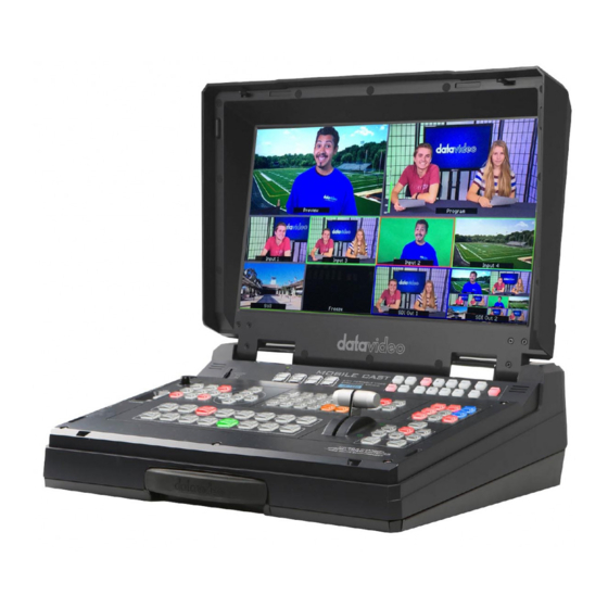
- Page 1 HD 6 CHANNEL PORTABLE VIDEO STREAMING STUDIO HS-1300...
-
Page 2: Table Of Contents
Contents FCC COMPLIANCE STATEMENT ........................4 WARNINGS AND PRECAUTIONS ........................ 4 WARRANTY ............................... 5 ............................5 TANDARD ARRANTY ............................5 HREE ARRANTY DISPOSAL ..............................6 CHAPTER 1 INTRODUCTION ........................7 ..............................7 EATURES ............................. 8 YSTEM IAGRAM CHAPTER 2 CONNECTIONS AND CONTROLS ....................9 ........................ - Page 3 SERVICE AND SUPPORT ........................... 87 Disclaimer of Product and Services The information offered in this instruction manual is intended as a guide only. At all times, Datavideo Technologies will try to give correct, complete and suitable information. However, Datavideo Technologies cannot exclude that some information in this manual, from time to time, may not be correct or may be incomplete.
-
Page 4: Fcc Compliance Statement
This product should only be operated from the type of power source indicated on the marking label of the AC adapter. If you are not sure of the type of power available, consult your Datavideo dealer or your local power company. -
Page 5: Warranty
Warranty Standard Warranty Datavideo equipment are guaranteed against any manufacturing defects for one year from the date of purchase. The original purchase invoice or other documentary evidence should be supplied at the time of any request for repair under warranty. -
Page 6: Disposal
Disposal For EU Customers only - WEEE Marking This symbol on the product or on its packaging indicates that this product must not be disposed of with your other household waste. Instead, it is your responsibility to dispose of your waste equipment by handing it over to a designated collection point for the recycling of waste electrical and electronic equipment. -
Page 7: Chapter 1 Introduction
Chapter 1 Introduction HS-1300 features an easy-to-use video streaming and recording appliance for professional video producers who need to simultaneously stream a live event and record the master quality version for post-editing. The HS-1300 is a cost effective 6 channel broadcast-quality hand-carry mobile switcher, it is designed for live events and TV programs that need to mix a variety of video and audio sources. -
Page 8: System Diagram
1.2 System Diagram... -
Page 9: Chapter 2 Connections And Controls
Chapter 2 Connections and Controls Power Switch 3 PIN XLR Audio Input 1 – 2 4 PIN XLR Power Input Connector GPI Output Connector Monitor HDMI IN (External Video Input) Ethernet Port HDMI Video Input 1 – 2 Tally Signal Output HD-SDI Video Input 1 –... -
Page 10: Rear Panel Connections
2.1 Rear Panel Connections 1. POWER SWITCH Switches the power On / Off. 2. DC Power Input Connect the supplied 12V 5A PSU to this 4 PIN XLR socket. 3. Monitor HDMI IN (External Video Input) The HS-1300 provides a useful connection for confidence monitoring of HDMI sources on location. - Page 11 7. HDMI Video Output All three HDMI ports output Program video. 8. AUDIO Input 1-2 Supports two XLR Balanced Audio Input channels. 9. GPI Output The GPI socket can be used for simple external control. Note: Please configure GPI settings in the Switcher Menu. 10.
-
Page 12: Switcher Control Panel
2.2 Switcher Control Panel User Memory and Function Keys User Memory User Memory buttons 1-6 allow the user to recall and load previously saved switcher settings. SHIFT There are 12 user memory locations. Under normal circumstances, Buttons USER 1 to 6 represent user memory locations 1 to 6. To load settings saved in locations 7 to 12 to buttons USER 1-6, simply press the SHIFT button. -
Page 13: Keyer Source
Keyer Source Selection of Keyer Source from Program / Preset Row Keep holding down one of these buttons to enter key select mode and fill select mode. Select key source from the Program row and fill source from the Preset row. The selected source button will flash. -
Page 14: Program & Preview Source Row
Transitions can be performed manually using the T-Bar or automatically by using the SPEED and AUTO TAKE buttons. Vertical Wipes from Centre to Left and Vertical Wipe Left to Right Right sides Upper Left corner Wipe to Lower Box Wipe from Centre to outside edges Right corner Diamond Wipe from Centre to Circle Wipe from Centre to outside... -
Page 15: Transition Effect
Transition Effect Fade To Black, this button fades the current video program source to black. When pressed again it acts in reverse from complete black to the currently selected program video source. SPEED There are three speed buttons which can be defined by the user. By pressing a speed button the user is choosing the rate of transition or time taken when using the AUTO TAKE button. -
Page 16: Audio Control
T-Bar This performs a manually controlled transition from the current program source to the selected preset source. The selected transition wipe or dissolve will be used. When the T-Bar has travelled as far as it can go, the transition between sources is complete. The T-Bar has indicators next to it, which light when the transition is complete. - Page 17 Source Select Buttons Select the type of source you are using - HDMI, MV (multi-view), PGM (program). HDMI Switch the 17.3” built-in monitor to display the video source plugged into the MONITOR HDMI IN port. BLUE Press this button to eliminate the red and green component of input signals.
- Page 18 RECORD Press the RECORD button to start video recording. STREAM Press the STREAM button to start video streaming. SD Card Slot Insert an SD card into the SD card slot for video recording. Note: Do not remove SD card while it is being written as doing so may result in corrupted video files.
-
Page 19: Chapter 3 Network Setup
DHCP / LAN network. An RJ-45 Ethernet cable. Windows 7/8/10 laptop or PC. The Datavideo Switcher Image Import/Export software. Instructions 1. First connect the HS-1300 and the Windows computer together using an RJ-45 ethernet cable. -
Page 20: Installing The Switcher Image Import/Export Software To A Windows Computer
HS-1300 with a computer then please follow the instructions in the previous section. Please download the latest software from the Datavideo HS-1300 web page. See: www.datavideo.com The install executable file [.msi] will be called SwitcherImageImEx_vXXXX.msi The vXXXX represents the latest version number. -
Page 21: Router Based Dhcp Setup
To help guide you, we have included a simplified network setup example below, further advice may be available through your dealer locally or your Datavideo regional office. To create this simple dedicated HS-1300 IP network you will need: ... -
Page 22: Setting The Target Ip Address With The Switcher Image Import/Export Software
5. The DEFAULT GATEWAY number displayed should be the router’s current IP address. 6. Enter the DEFAULT GATEWAY IP address into the address bar of the computer’s web browser. 7. The web browser should display the login window for the router. Enter the router’s login and/or password. - Page 23 If the network settings are wrong then you may not be able to access the HS-1300. Always keep a note of the last IP settings used and change these settings carefully to avoid problems. Target IP address – This IP address is the location on the local network, or the internet, where the software can talk to the HS-1300.
-
Page 24: Chapter 4 Switcher Osd Menu
Chapter 4 Switcher OSD MENU 4.1 Overview When the MENU button is pressed the Main Menu list is displayed on the HS-1300 monitor. This section covers the Menu options in the order that they appear on the HS-1300 monitor. These settings may also appear in more detail elsewhere in this instruction manual. - Page 25 Parameter for transparency of the overall foreground key Opac image, ranging from 0% to 100%. Bars Matte Input 6 Input 5 Input 4 Key Source Selections Input 3 Key Source Input 2 Input 1 Black Fill Source Selection from Bars /Matte /Input 6 /Input 5 Fill /Input 4 /Input 3 /Input 2 /Input 1 /Black Left...
- Page 26 Vertical PIP Position Size PIP Size Luma PIP Border Luma PIP Border Color Saturation Border PIP Border Color Hue Width PIP Border Width Left Left Edge of the Crop Right Right Edge of the Crop Crop Size Size of the Crop Top Edge of the Crop Bottom Edge of the Crop Fine...
- Page 27 Freeze Live Input 6 Input 5 Input 4 Input 3 Input 2 Input 1 Input 6 Input 5 Input 4 Input 3 Input 2 Input 1 Input 6 Input 5 Input 4 Input 3 Input 2 Input 1 Crosspoint Input 6 Input 5 Input 4 Input 3...
- Page 28 MultiV (Multi view) HDMI (17.3” Built-in 1080i Monitor Resolution) 1080p Mode ON/OFF Input 6 Input 5 Input 4 Input 3 Input 2 Input 1 Audio Follow External SDI 1 SDI 1 Audio Enable (ON)/Disable (OFF) SDI 2 SDI 2 Audio Enable (ON)/Disable (OFF) HDMI (17.3”...
- Page 29 Sets the Frame store mode of Input 1 to Clip / Still / Freeze / Live Sets the Frame store mode of Input 2 to Clip / Still / Freeze / Live Sets the Frame store mode of Input 3 to Clip / Still / Freeze / Live Freeze Sets the Frame store mode of Input 4 to Clip / Still /...
-
Page 30: Functions
4.2 Functions The HS-1300 HD 6-Channel Portable Video Studio offers the user an OSD menu to perform several image effect configurations, such as Picture-in-Picture, keyers, downstream keys, still pictures and etc. The user can also configure the I/O by selecting the Inputs and Outputs options. In addition, under the setup options, the user is allowed to set the menu color, size, position and language. -
Page 31: Keyer
Position Position allows the user to adjust the centre position of some wipes (e.g Circle & Elipse). X represents the horizontal position and Y represents the vertical position. Positive value: position the wipe centre to the right Positive value: move the wipe centre up Negative value: position the wipe centre to the left Negative value: move the wipe centre down Zero value: Position the wipe centre at the screen... -
Page 32: Chroma
Lift adjusts the dark/black areas of the key image. Gain adjusts the light/white areas of the key image. Opacity adjusts the transparency of the overall foreground key image. Key Source This sub-option allows the user to assign the key source; various options are listed below: Bars Matte Input6... -
Page 33: P-In-P
Key Range (KRange): Key Range sets the range of hues or colors (0 – 360 degrees) that closely match the background color to be keyed. The user can start with a value of 120 degrees and this value can be fine- tuned up or down depending on the setup of the green or blue screen studio. -
Page 34: P-In-P Lite
Y-Value Positive value: move the P-in-P window up. Negative value: move the P-in-P window down. Zero value: Position the P-in-P window at the center. Size Ranges from 0 to 100 with 1% being the smallest and 100 being the largest. So 50% would represent a P-in-P window which is half the size of the background image. -
Page 35: Inputs
Position The user can adjust the horizontal position of the P-in-P window by adjusting the X value. Positive X value positions the P-in-P window to the right. Negative X value positions the P-in-P window to the left. Zero X value positions the P-in-P window at the center. Border P-in-P window border color can be set by adjusting the Luma, Saturation and Hue values. -
Page 36: Outputs
Freeze “Freeze” allows the user to load an image to Inputs 1-6 from one of the four sources listed as follows: Still Freeze Live Crosspoint In this sub-option, the user can shuffle the contents of Inputs 1-6 without changing the hardware connections at the back of the machine, or even assign multiple inputs to the same source. -
Page 37: Stills
Mode (On/Off): The HS-1300 can only accept external audio using the analogue XLR inputs on the rear panel. Ideally a master audio mixer would be used alongside the HS-1300. A Datavideo AM-100 or AD-200 could be considered. By changing the Audio sub option from ON to OFF will mute the incoming XLR audio from the external master audio mixer. -
Page 38: User Mems
Load Still Upon selecting “Load Still”, the user can then choose the memory location from which the still image is loaded. The following are the destinations to which the still image can be loaded: Input 6 Input 5 ... -
Page 39: Setup
Load Memory Use the up/down arrow to scroll to the desired memory location (1-999) and load the saved setting by selecting “Load”. The user can also press one of the USER memory shortcut buttons (1-6) on the control panel as a quick way of loading those previously saved User configurations. Save Memory Use the up/down arrow to scroll to the desired memory location and save the current setting by selecting “Save”... - Page 40 Menu color: the available colors are blue and grey Options of Menu Transparency are listed below: 0: No Transparency 1: Background 50% Transparent (buttons not Transparent) 2: All Menu 50% Transparent Menu Size The menu size options are: 1. Normal 2.
-
Page 41: Chapter 5 Video Streaming
The HS-1300 Portable Video Studio includes a built-in Video Streaming Server (NVS-31) allowing the user to stream and record your program at the same time. From any HDMI input source, the Datavideo NVS-31 generates an H.264 encoded stream compliant with RTSP or RTMP protocols. While encoding the video at bit rates appropriate for live streaming, the Datavideo NVS-31 concurrently records a high-quality MP4 file to an SD card. -
Page 42: Web User Interface
There are basically two ways to establish connection between the NVS-31 and your computer: Connect an Ethernet cable from the NVS-31’s LAN port directly to your computer’s Ethernet port. Connect an Ethernet cable from the NVS-31’s LAN port to the same network switch as your computer. -
Page 43: Source
Source The video source is fixed onto PGM View only. In the Video Source column, you will be allowed to adjust video properties such as Brightness, Contrast, Hue, Saturation and Sharpness. These parameters range from 0 to 255. The Audio Source column currently indicates that the audio is embedded into HDMI video and is NOT reserved for future development. - Page 44 The encoder parameters are described below: Resolution The first step of encoder setup is to adjust the image size. The NVS-31 allows you to select a resolution from the list below. 1920 x 1080 1280 x 720 960 x 540 ...
- Page 45 Video Bitrate (bps) The bitrate of the video specifies the amount of information stored in the video. The higher the bitrate is, the clearer the video is. The bitrate ranges from 256K to 16M as shown in the table below. ...
-
Page 46: Record
25 20 15 10 5 3 2 1 Cropping The cropping feature allows the user to select a confined area of the camera video. X and Y parameters select the center of the video crop. After that, the user can then set W and H values to select the size of the crop. -
Page 47: Streaming
Loop Recording Loop recording allows the user record continuously to the disk. Select YES to enable loop recording and NO to disable. Recording File This text box displays the recording file name. Storage Information Column In this column, the user will be able to view the USB drive information such as the Vendor Name, Product Type, Disk Capacity and Disk Format Type. - Page 48 As soon as the stream is started successfully, you will be able to see the RTSP view link (Play URL) displayed as shown in the diagram below. To view the stream, open the Play URL in VLC Video Player.
- Page 49 Open VLC Media Player and click “Open Network Stream.” On the Open Media window, enter the Play URL “rtsp://192.168.1.151:8000/live” and then click the Play button to open the view window. RTMP Mode In RTMP mode, the NVS-31 can only send one data stream to one CDN or media server that supports the RTMP streaming protocol.
- Page 50 respective RTMP stream information. To start streaming, simply click the “Start Stream” button after the RTMP mode is configured. TS Mode In MPEG transport stream mode, the NVS-31 can send stream data directly to the viewer. On the streaming setup page, select the Encoder Source first and then enter the TS IP address and the TS port number.
-
Page 51: System
System The NVS-31 also allows the user to configure the system’s network settings, set account login credentials, update the device firmware, select the time, restore the factory defaults and reboot the system. Network Setting You are allowed to connect the NVS-31 to a network in DHCP or Static IP mode. Disable DHCP server if you want to connect to the NVS-31 on a fixed IP. - Page 52 Change the password in the Account Setup. Firmware Update From time to time Datavideo may release new firmware to either add new features or to fix reported bugs in the current NVS-31 firmware. To update the firmware, you must first click the Browse button to search for the firmware file on the disk.
- Page 53 Once the file is uploaded successfully, click the Update button to start the update. The device will reboot itself after the firmware is successfully updated. Time Setting Enter the device’s time setting for recording purpose. Specify your time server in the NTP field. System Related Click the Restore to Default button to reset the NVS-31 to factory defaults.
-
Page 54: Chapter 6 Advanced Operations
Chapter 6 Advanced Operations 6.1 Still Images This section will show you how to import still images from the PC to the switcher and load the imported file to the switcher. You are also allowed to export still images from the switcher to the PC for file editing. Export/Import Still Images to/from the PC The switcher’s Image Import/Export software (SwitcherImageImEx_vx.x.x.msi) allows the user to import still pictures from the PC to the designated Still number of the switcher and vice versa. - Page 55 4. Click “Install” 5. When you see the safety warning requesting for permission to allow an unknown publisher to make changes to the PC, please click “Yes” to continue.
- Page 56 6. Wait for the installation to finish. 7. After the setup is complete, you will see the following window; click “Finish” to launch SwitcherImageImEx immediately.
- Page 57 8. After the setup is finished, a shortcut will be created in Start Menu > Programs > datavideo > tools > SwitcherImageImEx 9. Click SwitcherImageImEx to open the program.
- Page 58 How to use 1. When the program is executed for the first time, it will automatically scan the network and if multiple network interface cards are found, please select the card that is on the same network as the device. 2.
- Page 59 4. After clicking Import-Export, you will be able to see four options which are Import Still, Import User, Import Clip and Export. 5. When in Import Still, click a Still number first and enter a location for storing the still. Then click Import Still again, the interface for selecting picture files will appear.
-
Page 60: Loading Still Images
Note: The latest software version can be downloaded from the product page. To update the software, it is recommended to remove the existing program first. Click “Start Menu > Programs > datavideo > tools > Uninstall” to remove the program. If the program is not removed, the user will be prompted that the PC already contains the same program during the reinstallation process. -
Page 61: Stinger Transition Effect
Grab Still Grab Still 1 Freeze Live 2 Live 3 Live Live 3. In the Load Still sub-option, first select the still picture that you would like to load (Still Num). The still picture preview is shown in the row right below the Load Still row. 4. -
Page 62: Importing The Clip For Stinger Transition Effect From The Pc
Restoring CH6 window for Live or Still mode If the Clip transition is no longer needed, you may free up the CH6 window for other modes of use such as Still and Live. Follow the steps outlined below to re-configure the CH6 source. 1. - Page 63 Click Setup on the MENU SELECT pane and if the connection between the HS- 1300 and the PC has been successfully established, you will be able to see the network information of your switcher. Select Import-Export from the yellow menu options. The clip number allows you to select a location where you can save the clip.
-
Page 64: How To Create The Png Sequence For Stinger Transition Effect
Note: The Switcher Image Import/Export utility does the conversion from bmp/png/jpg to the .pic file format. All you need is to give the utility a starting file location and it will give the utility an idea where to start linking all images up into a sequential animation file. Importing Clips Select “Import Clip”... - Page 65 2. The Render Queue will be displayed in the bottom pane.
- Page 66 3. Click Output Module and on the Main Options window, click the Format dropdown list and select PNG Sequence. 4. Click the Channels dropdown list and select the “RGB + Alpha” option. 5. Click “Output To” and then change the location where your files are rendered. Click Render after that. The next section outlines the file conversion procedure using the Media Encoder CC.
- Page 67 Media Encoder CC 1. Click Composition → Add to Media Encoder Queue (or alternatively, you can also click File Export Add to Media Encoder Queue). 2. Click blue fonts in Format/Preset fields to open the “Export Settings” window.
- Page 68 3. Click the Format dropdown list and then select PNG. 4. Click the Preset dropdown list and select “PNG Sequence with Alpha.” 5. Make sure “Export As Sequence” and “Include Alpha Channel” are checked and then click OK.
-
Page 69: Important Things To Note While Creating Stinger Transition Effects
Important things to note while creating Stinger Transition Effects When using Datavideo’s HS-1300 Multi-Channel Switcher to design and create the Stinger Transition Effects, in addition to being creative, there are a few things that you need to take into account of. -
Page 70: Chromakeyer
6.3 Chromakeyer Performing the configuration steps below will allow you to preview the keyer effect on the Multiview by simply pressing KEYER PGM or KEYER PVW buttons. Set up studio equipment including lights and the backdrop (Green/Blue). Press the “MENU” button to open the Keyer Setting Menu. -
Page 71: Dual Chromakey
Keyer Keyer Chroma Self Priority Keyer Ctrl Lift 0% Gain 1.0 Opac 100% Key Source Input 1 Fill Black CK Setup CK Auto 140 Luma 101% 160 K Fgnd 10% K Bgnd Range Hi-Light 0% Lo-Light 0% Bg-Supp Mask Left 0% Right 0% Bot Select “Chroma”... - Page 72 Select “Key 1” under the “Keyer” sub-option. Select the camera image to be chromakeyed under the “Key Source” sub-option. In this example, the source is “Input 1,” which is Channel 1. Adjust the left, right, top and bottom values of the “Mask” sub-option to set the chroma key range, which is the green backdrop size.
-
Page 73: User Memory
6.5 User Memory The user memory allows the user to save the current switcher settings to different presets. You will be able to import/export these memory presets from/to the PC. In this section, we will show you how you can import and export these user memory presets step by step. - Page 74 3. As soon as “Import User” is clicked, the PC hard disk browser window will open; select a .mem file to import a user settings file. 4. To export, simply click “Export” and the following window will open; select a preset number to export the user settings to the PC in .mem file.
-
Page 75: Loading User Memory Preset
Loading User Memory Preset The HS-1300 allows the user to load user memory presets saved on the machine to the Multiview screen. Please follow the steps outlined below to load the user memory preset. 1. Press the MENU button to open the OSD menu on the Multiview display. 2. -
Page 76: Chapter 7 Monitor Osd Menu Options
Chapter 7 Monitor OSD MENU Options The HS-1300 Monitor can be configured via an on screen menu. When the MENU button is pressed the Main Menu list is displayed on the monitor. This section covers the Menu options in the order that they appear on the monitor. -
Page 77: Main Adjust
7.1 Main Adjust The first menu option is the MAIN ADJUST. To access the MAIN ADJUST sub-menu, press enter and the Brightness sub-option will be highlighted. To adjust BRIGHTNESS press Enter again. Use the Up / Down buttons to change the setting and then press Enter to store the new value and return to the main menu. -
Page 78: Factory Reset
7.5 Factory Reset The monitor menu offers a Factory Reset option, which will return all the settings of the monitor to the factory defaults To reset the monitor press the MENU button and then use the UP / Down button to navigate to FACTORY RESET option. -
Page 79: Appendices
Switcher Firmware Update Procedure From time to time Datavideo may release new firmware to either add new features or to fix reported bugs in the current HS-1300 firmware. Customers can update the firmware themselves if they wish or they can contact their local dealer or reseller for assistance should they prefer this method. -
Page 80: Gpi Connection
SAFETY FIRST The cabling required needs to be designed specifically to connect the HS-1300 to the chosen record or playback device as they are not all the same. The cabling required can be made by yourself or a competent technician. Please speak with your Dealer or local Datavideo office to get further help and advice. -
Page 81: Tally Outputs
Tally Outputs The HS-1300 has a D-sub 15 pin female tally output port. These connections provide bi-colour tally information to a number of other Datavideo products, such as the ITC-100 eight channel talkback system and the TLM range of LCD Monitors. -
Page 82: Frequently-Asked Questions
Frequently-Asked Questions This section describes problems that you may encounter while using HS-1300. If you have any questions, please refer to related sections and follow all suggested solutions. If problem still exists, please contact your distributor or the service center. No. -
Page 83: Dimensions
Dimensions All measurements in millimetres (mm) -
Page 84: Specifications
Specifications Connections Total 6 inputs Total Video Inputs 2 HDMI (RGB/YVU, 1080P/1080I/720P) 4 SDI (1080I/720P) Monitor External Input 1 HDMI Total Outputs 3 HDMI + 2 SDI SDI Audio Output (PGM output) Audio Input 2 x XLR (2 x Analogue) Internal Frame Synchronizers All 6 Inputs PGM Out... - Page 85 Standards 1080i 50/ 59.94/ 60Hz, Format Support 720p 50/ 59.94/ 60Hz, SDI Compliance SMPTE 292M (SDI output /PGM out) Video Sampling 4:2:2 10 bit Color Precision 4:2:2 10 bit Color Space 4:2:2 YUV HDMI Input Resolutions for 1280 x 720 59.94Hz 50Hz (720P) and Computers 1920 x 1080 59.94Hz 50Hz (1080p &...
- Page 86 TS over TCP/UDP (unicast & multicast) RTSP over HTTP/TCP/UDP (RTSP Elementary Streaming) Streaming Protocol RTMP (Publish) Web browser UI for configuration and control Control Socket commands Recording File System exFAT Recording File Format Setting Control Web UI for system configuration and control ...
-
Page 87: Service And Support
Oct-19.2018 Version E5...
Need help?
Do you have a question about the EPB-1340 and is the answer not in the manual?
Questions and answers