Table of Contents
Advertisement
Quick Links
Advertisement
Table of Contents

Related Manuals for JETWAY JRL116M-2F-M

Summary of Contents for JETWAY JRL116M-2F-M
- Page 1 Web Management User Guide JRL116M-2F-M & JRL116MP-2F-M (PoE support) User's Guide...
-
Page 2: Table Of Contents
Web Management User Guide Contents 1 Introduction ............................ 3 2 Hardware Description ........................4 2.1 Front Panel .......................... 4 2.2 LED Indicators ........................4 2.3 Rear Panel ........................... 4 3 Hardware Installation ........................5 3.1 Package contents ......................... 5 3.2 Switch Installation ....................... 5 3.3 Grounding the Switch ...................... -
Page 3: Introduction
Web Management User Guide 1 Introduction Power-over-Ethernet (PoE) eliminates the need to run DC power to other devices on a wired LAN. Using a Power-over-Ethernet system, installers only need to run a single Category-5 Ethernet cable that carries both power and data to each device. This allows greater flexibility in the locating of network devices and, in many cases, significantly decreases installation costs. -
Page 4: Hardware Description
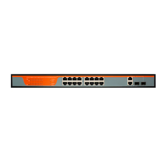
Web Management User Guide 2 Hardware Description 2.1 Front Panel The front panel consists of LED indications, reset button and 16x10/100 PoE ports + 2x10/100/1000 Uplink pots. 2.2 LED Indicators Power LED: The Power LED lights up when the switch is connected to a power source. Link/Act LED: Green (for megabit ports): Indicates that the port is running at 100M. -
Page 5: Hardware Installation
Web Management User Guide 3 Hardware Installation 3.1 Package contents Package contents include the following: PoE Switch:16x10/100 PoE ports with 2x10/100/1000 combo ports Ethernet Switch AC power cord Two (2) rack-mount pallet and Six (6) screws Four (4) adhesive-backed rubber feet ... -
Page 6: Grounding The Switch
Web Management User Guide Please be aware of following safety instructions when installing: Elevated Operating Ambient temperature - If installed in a closed or multi-unit rack assembly, the operating ambient temperature of the rack environment may be greater than room ambient. -
Page 7: Plugging In The Ac Power Cord
Web Management User Guide securely attached. 3.4 Plugging in the AC Power Cord Users may now connect the AC power cord into the rear of the switch and to an electrical outlet (preferably one that is grounded and surge protected). Power Failure As a precaution, the switch should be unplugged in case of power failure. - Page 8 Web Management User Guide Pin NO. Description Name Note Data transmission positive TPTXD1+ Output Data transmission negative TPTXD1- Output Data receive positive TPRXD2+ Input Data receive negative TPRXD2- Input Data Bi-directional positive BI_D3+ Bidirectional Data Bi-directional negative BI_D3- Bidirectional Data Bi-directional positive BI_D4+ Bidirectional Data Bi-directional negative...
-
Page 9: Troubleshooting
Web Management User Guide 4 Troubleshooting This section is intended to help solve the most common issues with the PoE Switch. Incorrect connections Every port on this switch can automatically detect either straight or crossover cables when you link it with other Ethernet devices but other devices may demand a specific cable type (depending on the device). -
Page 10: Getting Started
Web Management User Guide 5 Getting Started This chapter introduces the management interface of the switch. 5.1 Management Options The Switch can be managed through any port on the device by using the Web-based Management. Each switch must be assigned its own IP Address, which is used for communication with Web-Based Management. -
Page 11: Configuration
Web Management User Guide When the following logon dialog box appears, enter the username and password then click OK. The default username is admin and password is admin. 6 Configuration The features and functions of the switch can be configured for optimum use through the Web-based Management. -
Page 12: Administrator
Web Management User Guide 6.2 Administrator Administrator -> Authentication Configuration Here you can enter a new Username/Password and confirm it. Administrator -> System IP Configuration There are two ways for the switch to obtain an IP address: Static and DHCP (Dynamic Host Configuration Protocol). - Page 13 Web Management User Guide Administrator -> System Status Comment: By entering a Comment, the device can more easily be recognized on the LAN. Idle Time Security: It controls the idle time-out period for security purposes, when there is no action for a specific time span in the Web-based Management. If the current session times out (expires), the user is required a re-login before using the Web-based Management again.
-
Page 14: Port Management
Web Management User Guide After a correct password the switch will erase the old firmware first. After completing the erase you will see the screen as below. Specify the Firmware Path (or Browse for one) that you are going to use, and then click Update. The state will show ‘OK’ after completion, and ‘Fail’... - Page 15 Web Management User Guide In this page, the status of all ports can be monitored and adjusted for optimum configuration. Enable: Enable or disable the port’s connection Auto-Nege: Enable or disable port auto-NDI/MDIX Speed: Copper connections can operate in Forced Mode settings (1000M Full, 100M Full, 100M Halt, 10M Full, 10M Half), Auto, or Disabled.
- Page 16 Web Management User Guide TX (transmit) mode: Duplicates the data transmitted from the source port and forwards it to the Target Port. Click “all” to include all ports into port mirroring. RX (receive) mode: Duplicates the data that received from the source port and forwards it to the Target Port.
-
Page 17: Vlan Setting
Web Management User Guide 6.4 VLAN Setting VLAN Setting -> VLAN Mode A VLAN is a group of ports that can be anywhere in the network, but communicate as though they were in the same area. VLANs can be easily organized to reflect department groups (such as R&D, Marketing), usage groups (such as e-mail), or multicast groups (multimedia applications such as video conferencing), and therefore help to simplify network management by allowing users to move devices to a new VLAN without having to change any physical... -
Page 18: Per Port Counter
Web Management User Guide VLAN Setting ->VLAN Member Add VLAN: Click to create a new VLAN name and to select VLAN ports. The VLAN name should be less than 10 characters. To save the members in a group, click Add. VLAN Setting ->Multi to 1 Settings 6.5 Per Port Counter Per Port Counter ->... -
Page 19: Qos Setting
Web Management User Guide 6.6 QoS Setting QoS Setting -> Priority Mode QoS Setting -> Port, 802.1p ,IP/DS based... -
Page 20: Security
Web Management User Guide QoS Setting -> TCP/UDP Port Based 6.7 Security Security -> MAC Address Binding... -
Page 21: Spanning Tree
Web Management User Guide Security -> TCP/UDP Filter 6.8 Spanning Tree Spanning Tree -> STP Bridge Settings... - Page 22 Web Management User Guide Spanning Tree -> STP Port Settings Spanning Tree -> Loopback Detection...
-
Page 23: Trunking
Web Management User Guide 6.9 Trunking Trunking -> Link Aggregation Settings The Trunking function allows the switch to combine two or four ports together to increase bandwidth. Select the Trunking Groups, choose the Members to be grouped together, and then click Submit to activate the selected Trunking Groups. 6.10 DHCP Relay Agent DHCP Relay Agent ->... -
Page 24: Backup/Recovery
Web Management User Guide DHCP Relay Agent -> Relay Server DHCP Relay Agent -> VLAN MAP Relay Agent 6.11 Backup/Recovery Allow the current configuration settings to be saved to a file (not including the password), and if necessary, you can restore configuration settings from the file. -
Page 25: Miscellaneous
Web Management User Guide Backup or restore the configuration file to or from your local drive. Click Download to save the current settings to your disk. Click Browse to browse your inventories for a saved backup settings file. Click Update after selecting the backup settings file you want to restore. Note: Switch will reboot after restore and all current configurations will be lost. -
Page 26: Snmp Settings
Web Management User Guide 6.13 SNMP Settings 6.15 Logout Click this to end this session. Note: If you close the web browser without clicking the Logout button, it will be seen as an abnormal exit and the login session will still be occupied. 6.16 PoE PoE ->... - Page 27 Web Management User Guide PoE -> PoE Setting This section provides PoE (Power over Ethernet) Configuration and PoE output status of PoE Switch. Status: Can enable or disable the PoE function. Class: Class 0 is the default for PDs. However, to improve power management at the PSE, the PD may opt to provide a signature for Class 1 to 4.
- Page 28 Web Management User Guide Delay Mode: Enable or disable the port’s PoE Power Delay function. Delay Time: Set PoE power delay time (0~300). PoE -> PoE Scheduling PoE Schedule user can configure a duration time for PoE port as default value does not provide power.
- Page 29 Web Management User Guide As default value, all PoE Schedule Profile functions are disabled Please use a mouse to click on the block about what time you want to supply power for PoE port. PoE -> NTP Setting This section provide the NTP Configuration of PoE Switch System Time: Display current time information.
- Page 30 Web Management User Guide Set Port No.: Select the port witch you want to set IP Address. IP Address: Allow assign IP address witch you want to monitor. Checking Time: Select time interval of ping action (1-10Min). Enable Checking Port. No: Select the port witch you want to enable PoE Auto-check.
Need help?
Do you have a question about the JRL116M-2F-M and is the answer not in the manual?
Questions and answers