Table of Contents
Advertisement
Quick Links
Assembly and Operating Instructions for
Photographs are not to scale.
Specifications subject to change
without prior notice.
WARNING
FOR YOUR SAFETY
If you smell gas:
1.
Shut off gas to the appliance.
2.
Extinguish any open flame.
3.
Open barbecue lid or hood.
4.
If odour continues, discontinue use and
contact your local dealer.
PDF created with pdfFactory trial version
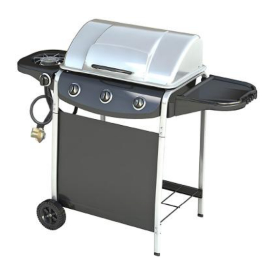
3 Burner with Side Burner Gas BBQ
•
For outdoor use only. Not for commercial use.
•
Use only Propane regulator 37mbar.
•
Read instructions before using the appliance. Failure to follow instructions could
result in death, serious bodily injury, and/or property loss.
•
Warning: accessible parts may be very hot. Keep young children away.
•
Do not move the appliance during use.
•
Turn off the gas supply at the gas bottle after use.
•
Any modification of the appliance, misuse, or failure to follow the instructions may
be dangerous and will invalidate your warranty. This does not affect your statutory
rights.
•
Retain these instructions for future reference.
•
Leak test your barbecue annually. Check the hose connections are tight and leak
test them each time you reconnect the gas bottle.
www.pdffactory.com
Model KS10013
FOR YOUR SAFETY
1.
Do not store or use petrol or other flammable
vapours or liquids in the vicinity of this or any
other appliance.
2.
A gas bottle not connected for use shall not be
stored in the vicinity of this or any other
appliance.
0359
Advertisement
Table of Contents

Related Manuals for Richmond KS10013

Summary of Contents for Richmond KS10013
- Page 1 Assembly and Operating Instructions for 3 Burner with Side Burner Gas BBQ Photographs are not to scale. Specifications subject to change without prior notice. Model KS10013 0359 • For outdoor use only. Not for commercial use. • Use only Propane regulator 37mbar.
-
Page 2: Parts List
A. Parts List Quantities vary according to model purchased. Specifications subject to change without prior notice. For more details on hardware, please see the corresponding Hardware Reference Diagram for your barbecue model. Code Part Grill assembly Lid handle Warming rack Cooking grill Heat tent Grease cup hanger... - Page 3 B1. Parts Diagram Quantities vary according to model purchased. Specifications subject to change without prior notice. For more details on hardware, please see the corresponding Hardware Reference Diagram for your barbecue model. PDF created with pdfFactory trial version www.pdffactory.com...
- Page 4 B2. Hardware Reference Diagram Specifications subject to change without prior notice. M4*8 Round Head Bolt 2 PCS M4*8 Pan Head Bolt 1PC PDF created with pdfFactory trial version www.pdffactory.com...
- Page 5 C. Assembly TOOLS NEEDED FOR ASSEMBLY: Medium size flat blade or Philips/cross-point screwdriver, adjustable spanner or metric spanner set. This barbecue requires two people for assembly. Please remove all packaging materials from all individual parts before assembling. Please lay out all nuts and bolts and check lengths before assembling. Whilst every care is taken during the manufacture of this product, care must be taken during the assembly in case sharp edges are present.
- Page 6 Fig 3 Fix the Leg Cap (B10) to the Right Front Leg (B1) and Right Rear Leg (B2) as Fig 3. Hammer the Leg Cap (B10) slightly to make it fix on the legs. Fig 4 Insert the Wheels (B5) to Left Front Leg (B3) and Left Rear Leg (B4) using the Axle (E7). Then fix the Axle (E7) by R pin (E6) as Fig 4.
- Page 7 Fig 5 Connect the Upper Support (B6) with the Left Front Leg (B3) and Left Rear Leg (B4) using the M6*25 bolt (E1) and M6 nuts (E3) as Fig 5. Repeat the same connection of the Upper Support (B6) with the Right Front Leg (B1) and Right Rear Leg (B2) using the M6*25 bolt (E1) and M6 nuts (E3) as Fig 5.
- Page 8 Fig 7a Fig 7b Fig 7c Fix the burner of the Grill Assembly (A1) using M6*25 bolt (E1) and M6 nut (E3) as Fig 7a. Set the Grill Assembly (A1) on the Upper Supports (B6) and fix it by M6*40 bolt (E4) and M6 nut (E3) as Fig 7b and 7c.
- Page 9 Fig 8a Fig 8b Hang the Grease Cup Hanger (A6) and Grease Cup (A7) on the Grill Assembly (A1) as Fig 8a and 8b. Fig 9b Fig 9a Place the Heat Tent (A5) on top of each burner of the Grill Assembly (A1). Align the Heat Tent (A5) with tabs on its end against slots on the firebowl back as Fig 9a.
- Page 10 Fig 10 Put the Washer (E12) between the Lid Handle (A2) and the Lid of the Grill Assembly (A1). Align the holes and fix the Lid Handle (A2) on the Lid of the Grill Assembly (A1) using M5*10 bolts (E5) as Fig 10.
- Page 11 Fig 12a Fig 12b Install the Side Table Assembly made in Step 9 to the Right Upper Support (B6) by M6*20 Shoulder Bolt (E9) as Fig 12a and 12b. Fig 13a Fig 13b Install the Side Burner Assembly (D1) to the Left Upper Support (B6) using M6*15 bolt (E8) as Fig 13a and 13b. PDF created with pdfFactory trial version www.pdffactory.com...
- Page 12 Fig 14a Fig 14b Fix the side burner valve of the Control Panel Assembly (B7) on the side burner panel bracket of the Side Burner Assembly (D1) using M4*8 round head bolt (E10) on the top and M4*8 pan head bolt (E13) at the bottom as Fig 14a.
- Page 13 Fig 15a Fig 15b Fig 15c Fix the Side Burner Electrode (D3) on the Side Burner Assembly (D1) using M4*8 bolt (E10) as Fig 15a. Put the Side Burner (D4) through the hole of Side Burner Assembly (D1). Adjust the burner venturi against the valve as Fig 15b.
- Page 14 Fig 16 Put the Side Burner Grate (D5) on the Side Burner Assembly (D1) and align with 3 holes as Fig 16. Fig 17 Put the Cooking Grill (A4) and Warming Rack (A3) on the Grill Assembly (A1) as Fig 17. PDF created with pdfFactory trial version www.pdffactory.com...
- Page 15 Fig 18 Attach the Front Canvas (B8) to the Left Front Leg (B3) and Right Front Leg (B1) and secure the position with the velcro on the canvas edge as Fig 18. Fig 19 Connect the Side Burner Electrode (D3) to the side burner valve of the Control Panel Assembly (B7) as Fig 19.
- Page 16 Fig 20 Complete the assembly as Fig 20. PDF created with pdfFactory trial version www.pdffactory.com...
-
Page 17: Installation
YOU MUST HAVE THE PROPER REGULATOR D. Important Information AND BOTTLE IN ORDER FOR THE BARBECUE TO OPERATE SAFELY AND EFFICIENTLY. USE OF Please read these instructions carefully before AN INCORRECT OR FAULTY REGULATOR IS assembly and use. DANGEROUS WILL INVALIDATE WARRANTY. -
Page 18: Operation
best cooking results. G. Operation G5. Lighting the Side Burner G1. Warning • Keep side burner free. • Before proceeding, make certain that you • Set the control knob to off and turn on the gas understand the IMPORTANT INFORMATION supply. -
Page 19: Technical Specifications
If this happens, Model Number KS10013 the gas should be immediately turned off at the Gas Category I3P (37) bottle. -
Page 20: Troubleshooting
L. Troubleshooting Problem Possible Cause Solution Burner will not light using the LP gas cylinder is empty Replace with full cylinder ignition system Faulty regulator Have regulator checked or replace Obstructions in burner Clean burner Obstructions in gas jets or gas hose Clean jets and gas hose Electrode wire is loose or disconnected on Reconnect wire...
Need help?
Do you have a question about the KS10013 and is the answer not in the manual?
Questions and answers