
Related Manuals for Sentinel CCTV MO53

Summary of Contents for Sentinel CCTV MO53
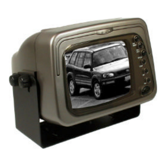
- Page 1 5” B&W RearView Monitor Installation & Operation MO53 (Monitor) FOR MORE INFORMATION WWW.STRATEGICVISTA.COM BEFORE OPERATING THIS SYSTEM, PLEASE READ THIS MANUAL THOROUGHLY AND RETAIN IT FOR FUTURE REFERENCE...
-
Page 2: Safety Precautions
Safety Precautions Before using this unit please read these operating instructions carefully. Take special care to follow th warnings indicated on the unit itself as well as the safety suggestions listed below. Keep them handy for future reference. Power source – The unit should be connected to power supply only of the type described in the operating instructions or as marked on the unit. -
Page 3: Table Of Contents
Table of Contents Safety Precautions………………………………………………………. Introduction……………………………………………………………….. System Contents………………………………………………………… Features…………………………………………………………………... Monitor Controls Front Panel & Back Panel …………………………………….… Monitor Installation……………………………….……………………… Connections……………………………………………………………… Operating Instructions………………………………………………….. Care & Maintenance……………………………………………………. Specifications……………………………………………………………. -
Page 4: Introduction
Introduction Thank you for purchasing the Sentinel 5” Black & White RearView Monitor. This system promotes and prevents backing-up and parking accidents, by allowing you to view or check on the traffic behind your vehicle, or when rounding corners (blind spot prevention). This monitor is suitable for waste trucks, RV campers, vans &... -
Page 5: Monitor Controls
Monitor Controls Front Panel Back Panel 1. Day/Night Switch • Normally this switch should be in the out position ( DAY) • When you view the picture at night or in a tunnel, etc, depress the switch to reduce the picture brightness ( NIGHT) 2. - Page 6 8. Power Connector • Insert the supplied power cable connector firmly until it is locked • To remove the power connector, press in the clip and pull out the connector, while holding the clip down 9. Video Output Connector Connect video to a second monitor or to a VCR/DVR 10.
-
Page 7: Monitor Installation
Monitor Installation • Install the monitor on a surface which will support more than 4 kg (10 lbs) of weight • Install the monitor away from any speaker mounted in the vehicle so that the picture is not distorted by the speaker’s magnetic field •... - Page 8 Monitor Installation The connection of the power plug is shown below: to Reverse Gear Relay (black) or Switch (Green) to DC 10-32V Fuse & Fuse Holder (Red) Note: The Red wire with the fuse holder should be connected to car or trucks ACC Terminal, the Green wire to reverse gear relay, and the Black wire to the chassis ground.
-
Page 9: Connections
Connections Back of Monitor DC10-32V CAM 1 CAM 2 VIDEO AUDIO Fuse Power cable lead (Red) L=15 m L= 15 m Ground lead (Black) Reverse power lead (Green) L= 5 m L= 1.8 m Camera A L=5 m Waterproof Connector L= 1.8 m Camera B Connect the RED wire to the (10V–32V DC) power terminal, which is... -
Page 10: Operating Instructions
Operating Instructions • When you turn the ignition key to the Accessory or ON position, power is supplied to the monitor and the monitor is in standby (If the Power button is not pushed in) • When you push the power button you can view the picture from the camera manually •... -
Page 11: Specifications
Specifications Monitor Video Format Picture Tube 5 inch Black & White CRT Picture Image Factory pre-set to reverse image Picture Resolution 450 TV lines at center Power Connector Red: Positive 10-32V input Green: Reverse Gear 10V – 32V input Black: Ground Inputs 4 pin multi connector 1) Video input: 1.0V p-p, 75 ohms, sync negative...
Need help?
Do you have a question about the MO53 and is the answer not in the manual?
Questions and answers