Table of Contents

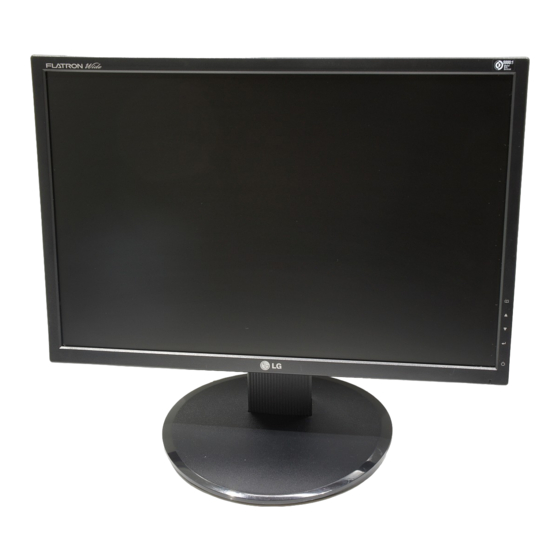
Summary of Contents for LG L194WT-BF
- Page 1 User’s Guide ake sure to read the before using the product. Keep the User's Guide(CD) in an accessible place for furture reference. ee the label attached on the product and give the information to your dealer when you ask for service.
- Page 2 On Safety Use only the power cord supplied with the unit. In case you use another power cord, make sure that it is certified by the applicable national standards if not being provided by the supplier. If the power cable is faulty in any way, please contact the manufacturer or the nearest authorized repair service provider for a replacement.
- Page 3 On Installation Do not allow anything to rest upon or roll over the power cord, and do not place the display where the power cord is subject to damage. Do not use this display near water such as near a bathtub, washbowl, kitchen sink, laundry tub, in a wet basement, or near a swimming pool.
-
Page 4: Connecting The Speaker
Connecting the speaker Place the monitor with its front facing downward on a soft cloth. nsert the protruding hook of the speaker in the direction of the slot in the back of the product. Slot Hook AUDIO IN After setting up the speaker, connect the Audio DC-In Cable to the back of the product. DC-OUT D-SUB DVI-D... -
Page 5: Connecting The Stand
Connecting the stand Place the monitor with its front facing downward on a soft cloth. Assemble the Stand Body into the product in the correct direction as shown in the picture. Make sure you push it until you hear it “click”. Assemble the Stand Base(Front, Rear) into the Stand Body in the correct direction. - Page 6 To remove the Stand:...
- Page 7 To remove the Stand Base:...
- Page 8 To remove the Stand Base:...
-
Page 9: Positioning Your Display
Positioning your display Adjust the position of the panel in various ways for maximum comfort. -5˚~20˚ Warning: When adjusting the angle of the screen, do not put your finger(s) in between the head of the monitor and the stand body. You can hurt your finger(s). - Page 10 Using the Computer Place the monitor in a convenient, well-ventilated location near your computer. Connect the signal cable. When attached, tighten the thumbscrews to secure the connection. Connect the power cord into a proper power outlet that is easily accessible and close to the display.
- Page 11 Side Jack Rear Speaker Out *Line Out <Jack of the PC sound card>...
- Page 12 Back Front Panel Controls...
-
Page 14: Screen Adjustment
Screen Adjustment Allow the display to stabilize for at least 30 minutes before making image adjustments. To make adjustments in the On Screen Display, follow these steps: Press the MENU Button, then the main menu of the OSD appears. To access a control, use the becomes highlighted, press the AUTO/SET Button. - Page 15 The following table indicates all the On Screen Display control, adjustment, and setting menus. Main menu Sub-menu PICTURE COLOR POSITION TRACKING SETUP FLATRON F-ENGINE NOTE The order of icons may differ depending on the model (A14~A18 ). Reference : Adjustable A : Analog Input D : Digital Input...
- Page 16 OSD (On Screen Display) menu languages on the monitor may differ from the manual.
- Page 17 Main menu Sub menu Description...
- Page 18 Main menu Sub menu Description...
- Page 19 Main menu Sub menu Description...
- Page 20 No image appears No image appears Do you see a "OSD LOCKED" message on the screen?
- Page 21 Display image is incorrect...
- Page 22 Display image is incorrect Have you installed the display driver?
- Page 23 Information in this document is subject to change without notice.
- Page 24 Information in this document is subject to change without notice.
- Page 25 Preset Modes (Resolution) Display Modes (Resolution) Horizontal Freq. (kHz) Vertical Freq. (Hz) Indicator MODE LED Color...
-
Page 26: Signal Connector Pin Assignment
Signal Connector Pin Assignment DVI-D Connector Signal(DVI-D) T. M. D. S. Data2- T. M. D. S. Data2+ T. M. D. S. Data2/4 Shield T. M. D. S. Data4- T. M. D. S. Data4+ DDC Clock DDC Data Analog Vertical Sync. T. - Page 29 Digitally yours...


Need help?
Do you have a question about the L194WT-BF and is the answer not in the manual?
Questions and answers