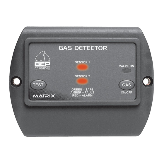
Summary of Contents for BEP 600 Series
- Page 1 Copyright © BEP Marine Limited, All rights reserved 600-GD & 600-GDL 600 SERIES GAS DETECTOR INSTALLATION OPERATING INSTRUCTIONS INST-600-GD-V5 29/11/07...
- Page 2 Copyright © BEP Marine Limited, All rights reserved This page has been deliberately left blank. Page 1 INST-600-GD-V5 29/11/07...
-
Page 3: Table Of Contents
Copyright © BEP Marine Limited, All rights reserved Table of Contents WARRANTY........................3 IMPORTANT ........................3 CAUTIONS WHEN USING GAS SENSORS ..............3 FEATURES........................4 SPECIFICATION ......................4 INTRODUCTION......................4 FAULT DETECTION ......................4 DIMENSIONS ........................5 WIRING DIAGRAM......................6 10 CONTROL HEAD INSTALLATION ................6 11 SENSOR INSTALLATION .....................7 12 OPERATION........................7... -
Page 4: Warranty
Copyright © BEP Marine Limited, All rights reserved 1 Warranty The warranty of this BEP MARINE LTD product is for Two Years from date of sale to original purchaser. BEP MARINE LTD does not assume the cost of removal or refitting of the product, or any other incidental cost that may arise, as the result of defect in materials or workmanship. -
Page 5: Features
7 Fault Detection The nominal alarm point of the 600 series is 20% of the LEL (Lower Explosive Limit) of LPG/CNG in Air. In the event of a gas leak and the alarm activating, close the manual valve on your gas bottles and open hatches to ventilate the area. -
Page 6: Dimensions
Copyright © BEP Marine Limited, All rights reserved 8 Dimensions Page 5 INST-600-GD-V5 29/11/07... -
Page 7: Wiring Diagram
Copyright © BEP Marine Limited, All rights reserved 9 Wiring Diagram Important Note: GDL ONLY If using one sensor, A link wire must be wired between B and G on the unused sensor side 10 Control Head Installation For ease of operation, the control head should be mounted in a convenient position close to your gas appliances and in a position where the control head can be seen and heard easily. -
Page 8: Sensor Installation
Copyright © BEP Marine Limited, All rights reserved 11 Sensor Installation The sensor is supplied with a 5-meter cable. For LPG and Petrol fumes, which are heavier than air, mount the sensor in a low dry position where the gas is likely to collect. The sensor must be mounted clear of bilge water. -
Page 9: Test / Alarm Mute Button
Copyright © BEP Marine Limited, All rights reserved 13 Test / Alarm Mute Button When the ‘TEST’ button is pressed in normal operation mode it will - Turn on the external alarm Turn on the blower Turn off the solenoid... -
Page 10: User Notes
Copyright © BEP Marine Limited, All rights reserved 17 User Notes Page 9 INST-600-GD-V5 29/11/07... - Page 11 Copyright © BEP Marine Limited, All rights reserved This page has been deliberately left blank. Page 10 INST-600-GD-V5 29/11/07...
- Page 12 Copyright © BEP Marine Limited, All rights reserved BEP MARINE BEP AUTOMOTIVE 13 Tarndale Grove 13 Tarndale Grove Albany, Auckland, N.Z. Albany, Auckland, N.Z. Ph: +64 9 415 7261 Ph: +64 9 415 7261 Fax: +64 9 415 9327 Fax: +64 9 415 9327 www.bepmarine.com...

Need help?
Do you have a question about the 600 Series and is the answer not in the manual?
Questions and answers