Table of Contents
Advertisement
Quick Links
ChannelPlus Telephone Entry Module
IMPORTANT INSTRUCTIONS
When using your telephone equipment, basic precautions should
always be followed to reduce the risk of fire, electric shock and
injury to persons, including the following:
1. Read and understand all instructions
2. Do not use this product near water, for example, near a bath
tub, wash bowl, kitchen sink, or laundry tub, in a wet
basement, or near a swimming pool.
3. Never push objects of any kind into this product through
cabinet slots as they may touch dangerous voltages.
SAVE THESE INSTRUCTIONS
4.
The
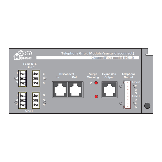
H612 Telephone Entry Module
of telephone connection to your system. Each unit provides
surge suppression for two lines and a master disconnect. Also,
Telephone Entry Module (surge,disconnect)
ChannelPlus model H612
From NTE
Line 2
1
6
Disconnect
Surge
Expansion
In
Out
Warning
Output
2
5
3
4
2
1
6
1
2
5
3
4
Line 1
Typical Installation
Install this jumper for normal
operation. Remove to disconnect
telephone service from the system.
CAT-5 jumper
(included)
H612
From telephone
company exchange
2 lines
Telephone Expansion Hub (4 lines x 8 phones)
ChannelPlus model H618
Expansion
Telephones
Ports
J8
J7
J6
J5
J3
RJ-45
110D-4
110D-4
110D-4
110D-4
110D-4
J10
In
RJ-45
J9
Out
Blu
Blu
Blu
Blu
Blu
Use CAT-3 or CAT-5
wires, 2 lines to 8
telephone wall
provides a superior method
each line has an LED
status indicator to warn
you of a surge event.
Telephone
Output
Line 2
2
3
5
Line 1
2
3
5
Each line is individually surge protected to 50 Joules and
4000 Amps. Some surges contain sufficient energy that
although your system has been protected, the surge
circuit will be unable to provide additional protection.
When this happens, the red light for that line will turn on
and the module needs to be returned for service.
Telephone Entry Module (surge,disconnect)
ChannelPlus model H612
From NTE
Line 2
1
6
Disconnect
Surge
Expansion
Telephone
In
Out
Warning
Output
Output
2
5
3
4
2
1
6
1
2
5
3
4
Line 1
2 lines to telephone
wall plates.
H618 telephone
expansion hub
J4
J2
J1
110D-4
110D-4
110D-4
R
4
T
R
3
T
Use self adhesive
R
2
T
sticker provided to
R
1
T
label the output I.D.
Blu
Blu
Blu
2
3
4
2
5
3
6
SAFETY INFORMATION:
a) Never install telephone wiring
during a lighting storm.
b) Never install telephone jacks in wet
locations.
c) Never touch uninsulated telephone
wires or terminals unless the
telephone line has been disconnected
at the network interface.
d) Use caution when installing or
modifying telephone lines.
Wire Color Codes
Modular connectors
6 position connectors
PR1
R
T
1
2
3
4
5
RJ-11
Single line telephones,
answering machines &
modems
Wiring a 110 connector
Keep sheath close to connector
Untwist .5" max.
Line 2
2
3
5
Line 1
2
3
5
Wiring a Cat-5 jack
Keep sheath
close to jack.
Follow color code for T568A jacks.
Position first pair to channel closest
to end of jack. (Do not untwist
conductor pairs more than 0.5"
from the termination point.)
Colors of OpenHouse wiring
CAT-5, 4 UTP
4
5
Telephone
6
(from telco)
Telephone
(in house)
Data
Security
RING
brown
pair 4
TIP
Cat5
brown/white
4 pair UTP
RING
green
TIP
pair 3
green/white
RING
orange
pair 2
TIP
orange/white
RING
pair 1
blue
TIP
blue/white
PR3
PR2
PR2
PR1
PR1
T
R
T
R
T
T
R
T
R
R
6
1
2
3
4
5
6
1
2
3
4
5
6
RJ-14
RJ-25
Dual line telephones &
Rare
answering machines
3 line KSU
2
1
110 punch-
110 punch-
down tool
down tool
Using a 110 punch-down tool,
push wires into channels
and trim.
Repeat for subsequent pairs.
tm
RG-6 coax
Downstream/External
(to TVs)
Upstream/Internal
(from modulators)
OpenHouse
tm
modules
attach from the top
1) Hook from the top
2) Swing into place
3) Push button to lock
1
3
Telephone Master Hub (4 lines x 6 phones)
Telephone Master Hub (4 lines x 6 phones)
ChannelPlus model H616
From
From
Expansion
Expansion
Telephones
Telephones
Telco
Telco
Ports
Ports
R
R
RJ31X
4
T
T
R
R
3
T
T
2
R
R
T
T
Out
1
R
R
T
T
2
Solid Color
Twisted-Pair Wire
blue
pair 3
white
yellow
pair 2
black
red
pair 1
green
8 position connectors
PR2
PR3
PR1
PR4
T
R
T
R
T
R
T
R
1
2
3
4
5
6
7
8
RJ-45 (wired to TIA T568A standard)
Ethernet (both 10BaseT and 100BaseT)
Structured wiring of phones and data lines
(There are other wiring standards. For
residential use, w
e recommend that
RJ-45
jacks be wired to the T568A standard.)
110 punch down tool
The 110 is a sophisticated insulation
displacement connection system. To
push the wire between the contact
blades, use only a
110 punch down
tool. Using
a screwdriver or needle
nose pliers may not seat the wire
properly and can damage the contacts.
Note order of colors
3
When all conductor pairs are
terminated, snap on strain relief caps.
Wiring Modular Plug (T568A)
Insert wires in this order:
White/Green
Green
White/Orange
Blue
White/Blue
Orange
White/Brown
Brown
Advertisement
Table of Contents

Related Manuals for Open House ChannelPlus H612

Summary of Contents for Open House ChannelPlus H612
-
Page 1: Typical Installation
3. Never push objects of any kind into this product through cabinet slots as they may touch dangerous voltages. SAVE THESE INSTRUCTIONS H612 Telephone Entry Module of telephone connection to your system. Each unit provides surge suppression for two lines and a master disconnect. Also,... - Page 2 ‘home known location.(This house rooms various from OpenHouse H612 Model Module Entry Telephone ChannelPlus ® multiplex technology , inc. 3001 Enterprise Street, Brea, 714-996-4100 800-999-5225 FAX 714-996-4900 Warranty Multiplex Technology, Inc. warrants this product to be free from defects in materials and workmanship for a period of one year from the date of purchase or MTI will repair, or at its option, replace the defective product.
Need help?
Do you have a question about the ChannelPlus H612 and is the answer not in the manual?
Questions and answers