Table of Contents
Advertisement
Quick Links
Advertisement
Table of Contents

Related Manuals for EMB Wallenstein HUF12000E


Summary of Contents for EMB Wallenstein HUF12000E
- Page 1 EMB MFG INC. EMB Manufacturing Inc. 4144 Boomer Line · St. Clements, On · N0B 2M0 · Canada Ph: (519) 699-9283 · Fax: (519) 699-4146 www.embmfg.com HUF12000E HUF12000EA PORTABLE GENERATOR MODEL HUF12000E & HUF12000EA OPERATOR'S MANUAL PRINTED IN CANADA REV 190713...
-
Page 2: Table Of Contents
TABLE OF CONTENTS WARRANTy .........................3 INSPECTION REPORT ....................4 SERIAL NUMBER LOCATION ..................5 INTRODUCTION .....................6 SAFETy ......................7 2.2 EQUIPMENT SAFETY GUIDELINES ............9 2.3 SAFETY TRAINING ...................10 2.5 PREPARATION ..................11 2.6 MAINTENANCE SAFETY ................11 2.7 OPERATING SAFETY ................12 2.8 REFUELING SAFETY ................12 2.9 STORAGE SAFETY...................12 2.10 BATTERY SAFETY ..................12 2.11 GAS MOTOR SAFETY ................13 2.12 SIGN-OFF FORM ..................14 SAFETy SIGN LOCATIONS ...............15... -
Page 3: Warranty
• any device or accessories installed by parties other than an authorized EMB dealer or distributor Engines are covered by the manufacturer of the engine and covered by the warranty period specified by that manufacturer. -
Page 4: Inspection Report
WALLENSTEIN PORTABLE GENERATOR INSPECTION REPORT This form must be filled out by the dealer and signed by both the dealer and the customer at the time of delivery. Customer’s Name Dealer Name Address Address City, State/Province, Code City, State/Province, Code Phone Number ( ) Phone Number ( ) Contact Name Model Serial Number Delivery Date SAFETy DEALER INSPECTION REPORT ____ Fasteners Tight ____ All Decals Installed ____ Check Electrical Connections ____ Guards and Shields Installed and Secured ____ Check Engine Fluid Levels ____ Review Operating and Safety Instructions I have thoroughly instructed the buyer on the above described equipment which review included the Operator’s Manual content, equipment care, adjustments, safe operation and applicable warranty policy. Date Dealer’s Rep. Signature The above equipment and Operator’s Manual have been received by me and I have been thoroughly instructed as to care, adjustments, safe operation and applicable warranty policy. -
Page 5: Serial Number Location
SERIAL NUMBER LOCATION Always give your dealer the serial number of your Wallenstein Portable Generator when ordering parts or requesting service or other information. The serial number plate is located where indicated. Please mark the numbers in the spaces provided for easy reference. Generator Serial Engine Serial HUF12000EA HUF12000E SERIAL NUMBER LOCATION Model Number ____________________________________________________ Generator Serial Number ___________________________________________ Engine Serial Number _____________________________________________... -
Page 6: Introduction
INTRODUCTION Congratulations on your choice of an Wallenstein Portable Generator to compliment your operation. This equipment has been designed and manufactured to meet the needs of a discerning person, operator or industry that needs portable electrical power. Safe, efficient and trouble free operation of your Wallenstein Portable Generator requires that you and anyone else who will be using or maintaining the generator, read and understand the Safety, Operation, Maintenance and Trouble Shooting information contained within the Operator's Manual. HUF12000E HUF12000EA This manual covers the Wallenstein Portable Generator Models HUF12000E and HUF12000EA. Use the Table of Contents or Index as a guide to locate required information. Keep this manual handy for frequent reference and to pass on to new operators or owners. Call your Wallenstein dealer or the Distributer if you need assistance, information or additional copies of the manu- als. OPERATOR ORIENTATION - The directions left, right, front and rear, as mentioned throughout this manual, are determined when standing and looking at the electrical panel. -
Page 7: Safety
SAFETy SAFETy ALERT SyMBOL This Safety Alert symbol means The Safety Alert symbol identifies ATTENTION! BECOME ALERT! important safety messages on the yOUR SAFETy IS INVOLVED! Wallenstein Portable Generator and in the manual. When you see this symbol, be alert to the possibility of personal injury or death. Follow the instructions in the safety message. Why is SAFETY important to you? Accidents Disable and Kill 3 Big Reasons Accidents Cost Accidents Can Be Avoided DANGER SIGNAL WORDS: - Indicates an imminently hazardous situation that, if not avoided, will result in death or serious injury. This Note the use of the signal words DANGER, signal word is to be limited to the WARNING and CAUTION with the safety... - Page 8 GENERAL SAFETy SAFETy 1. Read and understand the Op- yOU are responsible for the SAFE operation and erator’s Manual and all safety maintenance of your Wallenstein Portable Gener- signs before using, maintain- ator. yOU must ensure that you and anyone else ing, adjusting or cleaning the who is going to use, maintain or work around the Portable Generator. Portable Generator be familiar with the using and maintenance procedures and related SAFETy 2. Have a first-aid kit available information contained in this manual. This manual for use should the need arise will take you step-by-step through your working and know how to use it. day and alerts you to all good safety practices that should be used while using the Portable Genera- tor. 3. Have a fire extinguisher available for use should the need arise and know Remember, yOU are the key to safety. Good how to use it. safety practices not only protect you but also the people around you. Make these practices a work- ing part of your safety program. Be certain that EVERyONE using this equipment is familiar with the recommended using and maintenance proce- 4. Wear appropriate dures and follows all the safety precautions. Most protective gear. This accidents can be prevented. Do not risk injury or...
-
Page 9: Equipment Safety Guidelines
EQUIPMENT SAFETy GUIDELINES 1. Safety of the operator and bystanders is one 7. Never exceed the limits of a piece of machin- of the main concerns in designing and de- ery. If its ability to do a job, or to do so safely, is in question - DON'T TRy IT. veloping equipment. However, every year many accidents occur which could have been avoided by a few seconds of thought and a 8. Do not modify the equipment in any way. Un- more careful approach to handling equipment. authorized modification may result in serious You, the operator, can avoid many accidents injury or death and may impair the function by observing the following precautions in this and life of the equipment. section. To avoid personal injury or death, study the following precautions and insist 9. In addition to the design and configuration of those working with you, or for you, follow this implement, including Safety Signs and them. Safety Equipment, hazard control and ac- cident prevention are dependent upon the 2. In order to provide a better view, certain awareness, concern, prudence, and proper photographs or illustrations in this manual training of personnel involved in the operation, may show an assembly with a safety shield transport, maintenance, and storage of the removed. However, equipment should never machine. Refer also to Safety Messages and be used in this condition. Keep all shields in operation instruction in each of the appropri-... -
Page 10: Safety Training
SAFETy TRAINING SAFETy SIGNS 1. Keep safety signs clean and legible at all 1. Safety is a primary concern in the design and manufacture of our products. Unfortunately, times. our efforts to provide safe equipment can be wiped out by a single careless act of an 2. Replace safety signs that are missing or have operator or bystander. become illegible. 2. In addition to the design and configuration of 3. Replaced parts that displayed a safety sign should also display the current sign. equipment, hazard control and accident pre- vention are dependent upon the awareness, concern, prudence and proper training of 4. Safety signs displayed in Section 3 each have a part number in the lower right hand corner. personnel involved in the operation, transport, maintenance and storage of this equipment. Use this part number when ordering replace- ment parts. 3. It has been said, "The 5. Safety signs are available from your author- best safety feature is an ized Distributor or Dealer Parts Department or informed, careful opera- the factory. tor." We ask you to be that kind of an operator. It is the operator's responsibility to read and under- How to Install Safety Signs:... -
Page 11: Preparation
PREPARATION MAINTENANCE SAFETy 1. Never use the engine and machine until you 1. Good maintenance is your responsibility. Poor have read and completely understand this maintenance is an invitation to trouble. manual, the Engine Operator's Manual and each of the Safety Messages found on the 2. Follow good shop practices. safety signs on the engine and machine. - Keep service area clean and 2. Personal pro- dry. tection equip- - Be sure electrical ment including outlets and tools hard hat, safety are properly glasses, safety grounded. shoes, and - Use adequate gloves are rec- light for the job at ommended dur- hand. ing assembly, installation, operation, adjustment, maintain- 3. Make sure there is ing, repairing, removal, cleaning, or moving plenty of ventilation. Never operate the en- the unit. Do not allow long hair, loose fitting... -
Page 12: Operating Safety
OPERATING SAFETy REFUELING SAFETy 1. Read and understand operator's manual before 1. Handle fuel with care. It is highly flammable. starting. Review safety instructions annually. 2. Allow engine to cool for 5 minutes before refu- 2. Stop and disable engine, remove ignition key elling. Clean up spilled fuel before restarting and place in your pocket and wait for all mov- engine. ing parts to stop before servicing, adjusting or repairing. 3. Do not refuel the machine while smoking or when 3. To prevent electrical shocks, do not operate near open flame or sparks. this generator in the rain or with wet hands. It should be grounded in damp or highly conduc- 4. Fill fuel tank outdoors. tive conditions. -
Page 13: Gas Motor Safety
2.11 GAS MOTOR SAFETy 14. DO NOT crank engine with spark plug removed. If engine is flooded, crank until engine starts. BEFORE STARTING ENGINE, READ 15. DO NOT strike flywheel with a hard object or AND UNDERSTAND THE OPERATING metal tool as this may cause flywheel to shatter AND MAINTENANCE INSTRUCTIONS in operation. Use proper tools to service engine. THAT CAME WITH yOUR ENGINE. 16. DO NOT operate engine without a muffler. Inspect periodically and replace, if necessary. If engine WARNING: DO NOT is equipped with a muffler deflector, inspect pe- riodically and replace, if necessary with correct 1. DO NOT run engine in an enclosed area. Ex-... -
Page 14: Sign-Off Form
2.12 SIGN-OFF FORM Wallenstein follows the general Safety Standards specified by the American Society of Agricultural and Biological Engineers (ASABE) and the Occupational Safety and Health Administration (OSHA). Anyone who will be using and/or maintaining the Portable Generator must read and clearly understand ALL Safety, Usage and Maintenance information presented in this manual. Do not use or allow anyone else to use this generator until such information has been reviewed. Annually review this information before the season start-up. Make these periodic reviews of SAFETY and OPERATION a standard practice for all of your equipment. We feel that an untrained operator is unqualified to use this machine. A sign-off sheet is provided for your record keeping to show that all personnel who will be working with the equipment have read and understand the information in the Operator’s Manual and have been instructed in the operation of the equipment. SIGN-OFF FORM DATE EMPLOyEES SIGNATURE EMPLOyERS SIGNATURE... -
Page 15: Safety Sign Locations
SAFETy SIGN LOCATIONS The types of safety signs and locations on the equipment are shown in the illustrations that follow. Good safety requires that you familiarize yourself with the various safety signs, the type of warning and the area, or particular function related to that area, that requires your SAFETY AWARENESS. • Think SAFETY! Work SAFELY! • Read and understand operator's manual before starting. Review safety instruc- tions annually. • Stop and disable engine, remove ignition key and place in your pocket and wait for all moving parts to stop before servicing, adjusting or repairing. •... -
Page 16: Assembling
ASSEMBLING The machine comes from the factory in a shipping crate and configuration. A lways use tools equipment and forklifts of appropriate size and capacity for the job. Always use 2 men when lifting, moving and assembling the machine. When the machine is shipped, follow this procedure when preparing for the customer: 1. Clear the area of bystanders especially small children before starting. 2. Move the machine to the assembly area. Be sure there is sufficient clearance to access the machine from all sides. TyPICAL CRATING 3. Remove the lid and lay to the side. 4. Use a hoist or a crane to lift the unit out of its crate. -
Page 17: Install Battery
INSTALL BATTERy: 6. Install the hold down strap onto the "J" 1. Remove cables, clamps and brackets hooks over the battery. from their shipping position. 7. Tread on the wing nuts, snug up tightly. 2. Bring a battery to the machine. 8. Attach cable from the starter solonoid 3. Lay out components. to positive (+) battery post and tighten 4. Position battery in its tray. sucurely. 5. Install the threaded "J" hooks into the bat- 9. Attach the cable from the ground post on tery tray. the starter to the negative (-) post on the battery (neutral is bonded to the frame) Hold Down Strap Wing Nut "J" Hook Battery Cable Starter Ground Post (-) Starter Solenoid (+) 36 Ah battery is recommended BATTERY SAFETY 1. Wear gloves and safety glasses or face shield 5. Keep all sparks and flames away from batter- when working on or near batteries. -
Page 18: Operation
OPERATION OPERATING SAFETy • Read and understand operator's manual before • Do not refuel the engine while it is in operation starting. Review safety instructions annually. or still hot. Do not refuel the engine near open flames, pilot lights or sparking electrical devices • Stop and disable engine, remove ignition key (e.g. power tools, welders or grinders). Do not and place in your pocket and wait for all mov- operate the generator near flammable products. ing parts to stop before servicing, adjusting or repairing. • The engine should be refuelled in a well-lit area. Avoid fuel spillage. • To prevent electrical shocks, do not operate this generator in the rain or with wet hands. It • Never allow children or unauthorized people should be grounded in damp or highly conduc- to operate or be around this machine. tive conditions. • Keep the working area clean and free of de- • Close and secure all guards, deflectors and bris to prevent tripping. Operate only on level shields before starting and operating. -
Page 19: Machine Components
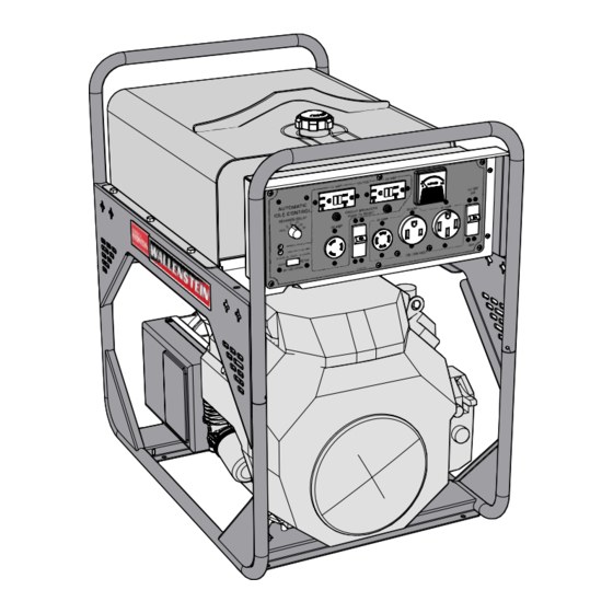
MACHINE COMPONENTS The Wallenstein HUF Portable Generator consists of The unit is designed to provide 120 V or 240 V 60 Hz a 20 hp Honda engine driving a 12,000 watt electrical power as a back up power supply at a remote location. generator. The series includes a load-sensing idle Each outlet is designed with a circuit breaker to protect relay for increased convenience. All control and against overload. The machine is neutral bonded to power outlets are mounted on the front of the frame for the frame. The battery and fuel tank are mounted in convenient access and operation. the frame for convenient access. Automatic Volt Meter Idle Control Volt Meter Main Switch Main Switch HUF12000EA HUF12000E Hour Meter 120/240 v Outlets 120 v Outlets 120/240 v Outlets / Oil Use Hours Meter 120 v Outlets... -
Page 20: Machine Break-In
MACHINE BREAK-IN PRE-OPERATION CHECKLIST Although there are no operational restrictions on the Efficient and safe operation of the Wallenstein Port- Portable Generator when used for the first time, it is able Generator requires that each operator reads recommended that the following mechanical items and understands the using procedures and all be checked: related safety precautions outlined in this section. A pre-operation checklist is provided for the opera- A. After operating for 1 hour: tor. It is important for both the personal safety and maintaining good mechanical condition that this 1. Re-torque all fasteners and hardware. checklist is followed. 2. Check condition of all electrical connec- Before operating Portable Generator and each time tions. -
Page 21: Controls
CONTROLS Before starting to work, all operators should famil- iarize themselves with the location and function of controls. This applies to all models. 5.51 ENGINE: Read the engine manufacturers operator's manual before starting for more detailed instructions. Ignition Switch: This key operated switch controls the electric power to the engine. OFF - Turn key fully counterclockwise to stop the electrical system power and turn the engine off. ON - Turn clockwise on detent to the run position. This is the position where the engine will continue to run. START -Turn fully clockwise to the last spring-loaded detent position to Choke engage the starter solenoid and start the engine. Release the key when the engine starts and it will return to the RUN position. Choke: This push/pull knob controls the position of the choke. Pull the knob out to close the choke for starting when the engine is cold. Ignition Push the knob in to open the choke as the engine warms. Always push the knob fully in Oil Alert HOURS 1/10 when operating the machine. Hour Meter Oil Alert: Honda GX630 The Oil Alert system is designed to prevent... -
Page 22: Electrical Controls: Huf12000E
5.52 ELECTRICAL CONTROLS: HUF12000E HUF12000E A. Voltmeter meter monitors and displays the volt- E. These outlets (6-50R & 14-50R) are used to age being produced by the generator. The top provide 120/240 Volt, 50 Amp power. scale displays the 120 Volt range and the bot- F. These 20 Amp breakers are used to protect the tom, the 240 Volt. 20 Amp 120 Volt outlets (B). Push the switch to reset. B. These two outlets (5-15R) are used to provide 120 Volt, 20 Amp power. G. This 30 Amp circuit breaker protects the two 30 Amp o ut l ets. ( C&D). M ove t he s witch u p t o e ngage C. This outlet (L5-30) is used to provide 120 Volt, the breaker and down to disengage. -
Page 23: Electrical Controls: Huf12000Ea
5.53 ELECTRICAL CONTROLS: HUF12000EA HUF12000EA A. Voltmeter meter monitors and displays the G. This 30 Amp circuit breaker protects the two voltage being produced by the generator. The 30 Amp out lets (C&D). Move the switch up to top scale displays the 120 Volt range and the engage the breaker and down to disengage. bottom, the 240 Volt. H. Main Switch / 50 Amp breaker protects the B. These two GFCI protected outlets (5-20R) are two 50 amp outlets (E) and is the master used to provide 120 Volt, 20 Amp power. overload for the generator. Move the switch C. This outlet (L5-30) is used to provide 120 Volt, up to engage the breaker and down to disen- 30 Amp power. gage the breaker. D. This outlet (L14-30) is used to provide 120/240 I. Automatic Idle Control is a fuel & time saving, Volt, 30 Amp power . convenience feature. See below for details. E. These outlets (6-50R & 14-50R) are used to IMPORTANT provide 120/240 Volt, 50 Amp power. A circuit breaker that trips repeat- F. These 20 Amp breakers are used to protect edly may indicate a problem. the 20 Amp 120 Volt outlets (B). Push the switch to reset. -
Page 24: Field Operation
FIELD OPERATION OPERATING SAFETy • Read and understand operator's manual before • Do not refuel the engine while it is in operation starting. Review safety instructions annually. or still hot. Do not refuel the engine near open flames, pilot lights or sparking electrical devices • Stop and disable engine, remove ignition key (e.g. power tools, welders or grinders). Do not and place in your pocket and wait for all mov- operate the generator near flammable products. ing parts to stop before servicing, adjusting or repairing. • The engine should be refuelled in a well-lit area. Avoid fuel spillage. • To prevent electrical shocks, do not operate this generator in the rain or with wet hands. It • Never allow children or unauthorized people should be grounded in damp or highly conduc- to operate or be around this machine. tive conditions. • Keep the working area clean and free of de- • Close and secure all guards, deflectors and bris to prevent tripping. Operate only on level... - Page 25 4. Starting the Generator: 5. Stopping: a. Plug in power cords from appliances or a. Turn the appliance off or unplug the electri- loads. cal load. b. Turn all the appliances or electrical loads b. Run the engine for approximately three off. minutes to allow the engine to cool. c. Refer to engine manual for detailed engine c. Turn engine off. starting procedure. 6.
- Page 26 8. Weather: 10. Electrical Component Condition: a. Do not operate in the rain or with wet hands. Keep the generator and work area dry to Always use electrical components that are in prevent shocks and shorts. Always ground good condition. Do not use electrical cords, the frame when operating in damp or wet plugs and connectors that are frayed, damaged, conditions. cracked or not in good condition. Electrical components that are not in good condition can b. Do not operate at temperatures above lead to shocks, shorts or sparking. Any of these...
- Page 27 11. Electrical Hazards: The generator is designed to generate an 13. Circuit Breakers: electrical current at a high enough power Each of outlets on the electrical panel is pro- level to get meaningful work done. However, tected with a circuit breaker to prevent over- power at these levels also includes the pos- loading the circuit. If a breaker trips, reduce sibility of electrical hazards. Some things to the load before re-setting the breaker. remember about electrical hazards include but • The two 120 volt 20 amp (5-15R) outlets are are not limited to: each protected by a 20 amp pop up circuit breaker. The HUF12000EA has the added a. Keep all electrical components in good feature of GFCI (5-20R) protected outlets. condition. • The 120 volt 30 amp (L5-30) and the 120/240 b. Do not operate with frayed, cracked or volt 30 amp (L14-30) receptacle are protected damaged parts. by a 30 amp breaker. If this breaker trips then the 20 amp circuit as well as the 30 amp c. Ground the frame if operating in damp or circuit will be off. wet conditions. • The 120/240 volt 50 amp (6-50R & 14-50R) receptacles are protected by a 50 amp d. Do not operate with wet hands.
- Page 28 14. Operating Hints: a. Position frame on a level area to minimize d. Always ground the frame to minimize the the chance of spilling fuel and maximize the chance of sparks, shocks or shorts. This is fuel capacity of the tank. Spilled fuel can be very important in damp, wet or rainy condi- ignited by a spark from the electrical power tions. system. e. Position the generator under cover to protect b. Do not refuel while the engine is running. Wait it from rain or bad weather. until the unit has cooled before refuelling. f. Do not operate when the ambient tempera- c. Keep the working area neat and clean to pre- ture exceeds 100° F (39° C) to prevent over- vent slipping and tripping. Prevent accidents heating. at the work site. g. Do not cover the unit during operation to prevent overheating.
-
Page 29: Moving
MOVING The generator is designed to be easily moved from one location to another. Review the following details on how the unit can be moved: Lift Eye 1. Lift Eye: The frame is designed with a lift eye that pro- vides an attach point for moving with an "A" frame, forklift, crane or other lifting system. 2. Wheel Kit: A wheel kit is available to make movement around the work area easier. Kit consist of handles and axle with tires The kit is easy to install and simply clamps on to the existing frame. Availalble with 10" tires (WK210) or Wheel Kit 13" tires (WK213) 3. Transporting: Fuel Line Shut- When transporting from location to location, follow this procedure: a. Run the engine (use the generator) until the fuel tank is empty or nearly empty. b. Turn the fuel line off. -
Page 30: Storage
STORAGE 5.8.2 REMOVING FROM STORAGE OPERATING SAFETy this procedure: • Store the unit in an area away from human 1. Remove the tarpaulin if covered. activity. 2. Install and connect the battery. • Do not permit children to play on or around the stored machine. 3. Bring the ignition key. • Store the unit in a dry, level area. Support the frame with planks if required. 4. Review and follow the pre-operation checklist. 5.8.1 PLACING IN STORAGE After the season's use or when the machine will not IMPORTANT... -
Page 31: Service And Maintenance
SERVICE AND MAINTENANCE SERVICE MAINTENANCE SAFETy 6.1.1 FLUIDS AND LUBRICANTS • Good maintenance is your responsibility. 1. Grease: Poor maintenance is an invitation to trouble. Use an SAE multipurpose high temperature grease with extreme pressure (EP) perform- • Follow good shop practices. ance. Also acceptable is an SAE multipur- pose lithium base grease. Keep service area clean and dry. Be sure electrical outlets and tools are 2. Engine Oil: properly grounded. See Honda engine owners manual for full de- Use adequate light for the job at hand. tail on oil type specific to operating conditions and capacity. • Make sure there is plenty of ventilation. Nev- er operate the engine of the towing vehicle in 3. Engine Gasoline: a closed building. The exhaust fumes may See Honda engine owners manual for full cause asphyxiation. -
Page 32: Service Record
6.1.3 SERVICE RECORD See Lubrication and Maintenance sections for details of service. Copy this page to continue record. ACTION CODE CHECK CLEAN R REPLACE CHANGE HOURS SERVICED MAINTENANCE 8 Hours or Daily CK Engine Oil Level CK Fuel Level 40 Hours or Weekly CL Air Cleaner 100 Hours or Monthly CH Engine Oil CH Engine Oil Filter R Fuel Filter R Air Cleaner Annually CL Machine MAINTENANCE By following a careful service and maintenance program for your machine, you will enjoy many years of trouble -free operation. -
Page 33: Trouble Shooting
TROUBLE SHOOTING The Wallenstein Portable Generator is designed to generate up to 10,000 continuous watts of power at any type of remote location. It is a simple and reliable system that requires minimal maintenance. In the following section, we have listed many of the problems, causes and solutions to the problems that you may encounter. If you encounter a problem that is difficult to solve, even after having read through this trouble shooting section, please call your local distributor or dealer. Before you call, please have this Operator's Manual from your unit and serial number ready. PROBLEM CAUSE SOLUTION Engine doesn't start. No fuel. Fill fuel tank. Fuel filter plugged. Replace fuel filter. Weak battery. Recharge or replace battery. Loaded electrically. Remove electric load. Breakers tripping. Electrical load too high. Reduce electrical load. -
Page 34: Specifications
SPECIFICATIONS MECHANICAL HUF12000E HUF12000EA Engine 20 hp / GX630 20 hp / GX630 Maximum Watts 12,000 12,000 Continuous Watts 10,000 10,000 Maximum Amps 100 / 50 100 / 50 120 V / 240 V Continuous Amps 84 / 42 84 / 42 Frequency 60 Hz 60 Hz Voltage 120 / 240 120 / 240 Fuel Tank Capacity 40 litres 40 litres Run Time 1/2 Load 10 hours 10 hours Full Load... -
Page 35: Bolt Torque
BOLT TORQUE CHECKING BOLT TORQUE The tables shown below give correct torque values for various bolts and capscrews. Tighten all bolts to the torques specified in chart unless otherwise noted. Check tightness of bolts periodically, using bolt torque chart as a guide. Replace hardware with the same strength bolt. ENGLISH TORQUE SPECIFICATIONS Bolt Torque* Bolt SAE 5 Diameter SAE 2 SAE 8 (N.m) (lb-ft) (N.m) (lb-ft) "A" (N.m) (lb-ft) 1/4" 5/16" 3/8" 7/16" 1/2" 9/16" 5/8" 3/4" 7/8" 1" 1320 METRIC TORQUE SPECIFICATIONS Bolt Torque* Bolt 10.9... -
Page 36: Index
INDEX Symbols 12 KVA ALTERNATOR ........19 LIFT EyE ............. 19, 29 20 AMP ...............27 LOUD NOISE ............. 11 30 AMP ...............27 LUBRICANTS ............31 50 AMP ...............27 MAIN SWITCH ...........19 ASABE ...............14 MODEL NUMBER ..........5 AUTOMATIC IDLE CONTROL .... 19, 23, 27 OFF ..............21 BATTERy ............17 OIL ALERT ............21...
Need help?
Do you have a question about the Wallenstein HUF12000E and is the answer not in the manual?
Questions and answers