Advertisement
Quick Links
Advertisement

Related Manuals for Marani DPA480


Summary of Contents for Marani DPA480
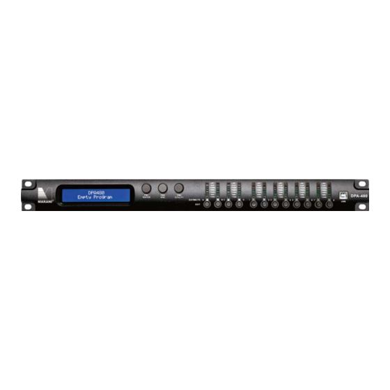
- Page 1 User Manual DPA480...
- Page 2 Described below are the functions of the front panel control buttons and encoders for the DPA480. • Getting Started As soon as the DPA480 is turned ON the device model name will appear in the LCD screen: 4 IN 8 OUT SPEAKER PROCESSOR...
- Page 3 • Encoders and ENTER, ESC buttons The DPA480 is equipped with 3 Relative Encoders, “PM1”, “PM2” and “PM3”, These encoders allow you to navigate the user interface and edit sections of the processor. They allow the user to navigate within the screen for the selection of sub-menus, pages and parameters and to select the values to be assigned during the editing operations.
- Page 4 MENU “UTILITY MENU” [Access by pushing the “UTILITY” button] PM1 Encoder PM2 or PM3 Encoder [to navigate between menus] [to chose option, then ENTER to load it; (*) indicates the selected option] 1 UTILITY MENU:..<< System Utilities >> ENTER SYSTEM UTILITY: Input Source <<...
- Page 5 MENU “Input A/B/C/D” Input Channels Editing [Access by pushing the “A/B/C/D” button] PM1 Encoder PM1 Enc. PM2 Enc. PM3 Enc. [to navigate between menus] [to chose values for the parameters, no need to confirm the chosen values, which are automatically loaded during the encoders use] 1.
- Page 6 PM1 N/A. Gain=-15dB … +15dB Q=Fixed Frequency=20Hz … 20000Hz Type= Hi -Shelv Q PM1 N/A. PM1 N/A. Gain=-15dB … +15dB Q=0.1 … 5.1 Frequency=20Hz … 20000Hz Type= Lo-Shelv 1/ Lo-Shelv 2 PM1 N/A. PM1 N/A. Gain=-15dB … +15dB Q=Fixed Type= Lo-Shelv Q PM1 N/A.
- Page 7 MENU “Output 1/2/3/4/5/6/7/8” Output Channels Editing [Access by pushing the “1/2/3/4/5/6/7/8” button] PM1 Encoder PM1 Enc. PM2 Enc. PM3 Enc. [to navigate between menus] [to chose values for the parameters, no need to confirm the chosen values, which are automatically loaded during the encoders use] 1.
- Page 8 20.0 Hz Bypass ENTER -> 20.0 Hz Bypass [Freq.] 20Hz Bypass PM1 N/A [Type/Slope] 20kHz LR -48 dB /Oct Slope=Bypass/ BW -6 dB/Oct / BW -12 dB/Oct / LR -12 dB/Oct / BS -12 dB/Oct / BW -18 dB/Oct / BW -24 dB/Oct / LR -24 dB/Oct / BS -24 dB/Oct / BW -36 dB/Oct / LR-36 dB/Oct / BW -48 dB/Oct / LR-48 dB/Oct / 9.
- Page 9 From the “System Utilities Sub-menu”, pushing “ENTER” and then using the “PM1” encoder for scrolling will give access to the following pages: Input Source: the DPA480 is equipped with 4 Analog Inputs (Balanced Female XLR) and 2 − AES Digital Input (RCA connector).and noise generator The “Input Source”...
- Page 10 UTILITY MENU: − Noise Generator: DPA480 equips with 2 types of noise generator: White Noise and Pink − Noise. SYSTEM UTILITY Noise Generator By pressing ENTER and rotating the “PM2” encoder, it is possible to select between those 2 choice: “Pink” or “White”. By rotating the “PM3” encoder, it is possible to set the value of level of white noise generator and pink noise generator, with whose range from 0dB to -40dB.
- Page 11 Firmware Version The correct Firmware Version is “V3.0.2” Program Utilities Sub-menu – this sub-menu allows you to access several options related to the DPA480 operating mode and to manage the presets stored and recallable within the Unit: UTILITY MENU Program Utilities Recall a Program: this page allows the Loading of a preset program by pressing the “ENTER”...
- Page 12 “ENTER” button and this will force the DPA480 to begin to load this selected preset and the following transitory screen will appear: Loading New Program ..PRESET 1 Once loaded the DPA480 will exit to the “Recall a Program” screen automatically and the...
- Page 13 Save a Program: this page allows you to store a new preset in the DPA480’s memory: − PROGRAM UTILITY Save a Program By pressing the ENTER button and rotating the “PM1” encoder, it is possible to scroll through the previously saved presets or the available empty locations (identified by “Empty Program”).
- Page 14 [Enter] to Overwrite 10: Stage 1 2x2 If you wish to proceed press “ENTER” again and the DPA480 will go ahead with the “Set Program Name” page and the subsequent overwrite on completion of the previously described storing process..
- Page 15 For example, if we want to delete the preset 10, “Stage 1 2x2”, the screen will be the following: [ENTER] to Delete. 10: Stage 1 2x2 Confirming the deletion by pressing “ENTER” again, will force the DPA480 to erase the selected preset and the following transitory screen will appear: Erasing Xover Memory..10: Stage 1 2x2...
- Page 16 IP address of the unit need to get from the router connected to the network the unit already in. Security Sub-menu – this sub-menu allows the User to set the parameters shown, lock the DPA480 and set a Password therefore limiting the unit's functions and controls to those who have only access to the appropriate Password.
- Page 17 When you select lock from the menu, the unit will be locked and the lock menu automatically exited. The screen will revert to the “Default” showing the current XOVER configuration and the preset selected and beside the preset’s name a “keylock” icon indicating that the DPA480 is locked.
- Page 18 Press the ENTER button one more time, the new password will be set successfully. Lock With Password: from the “Lock With Password” sub-menu: − There’s limitation to the editing function if the DPA480 is locked with password. All functions for this unit are banned, including MUTE A/B/C/D and MUTE 1/2/3/4/5/6/7/8 buttons. SECURITY UTILITY Lock With Password Press “ENTER”...
- Page 19 Remark 1: Select parameters the user desire by using 3 encoders. Once the user leaves this page, the above mentioned parameters would be saved to the DPA480 systems automatically. Remark 2: Exit this page by pressing “ESC” button.
- Page 20 In-A: Name N.Gate Bypass = On By pressing ENTER button in this page, an arrow “->” will show up on the left of the screen, and enter into the setting interface 1 of the noise gate: In-A In-A N.Gate ->Byp=On Thr=-80.0dBu By using the “PM2”...
- Page 21 By pressing ENTER button in this page, an arrow will appear on the left of the screen “->”. then use the “PM2” or “PM3” encoder for setting “Normal” or “Invert” Phase. RMS Cmp page– from this page, it is possible to set RMS Compressor for input channels. RMS Compressor can be set as “ON”...
- Page 22 +12dBu. EQ Byp page – in this page, it is possible to set EQ Bypass of input channels, with its selectable status of “ON” and “OFF”. Following is the example screen as Bypass ON: In-A In-A EQ Byp Bypass = On By pressing “ENTER”...
- Page 23 In-A In-A PEQ-01 ->Gain=0.0dB Q=0.40 By using “PM2” encoder, user can set the gain of current parametric equalization filter from -15dB to +15dB, and by using “PM3” encoder, it is possible to set the Q factor of current parametric equalization filter from 0.4 to 128. When the parametric equalization filter is selected as Hi-Shelv 1/ Hi-Shelv 2/ Lo-Shelv 1/ Lo-Shelv 2, by rotaing “PM1”...
- Page 24 In-A In-A PEQ-01 ->Frequency = 20Hz By using “PM2” or “PM3” encoder, it is possible to set current input PEQ filter’s frequency from the range of 20Hz to 20kHz. When the parametric equalization filter is selected as Low-Pass Q/ High-Pass Q, by rotaing “PM1” encoder, user can enter the setting interface 9 of current input parametric equalization filter: In-A In-A...
- Page 25 Note 1: If selected the desired options by using 3 encoders, the option would be set as a current one for the unit automatically, and will be stored in the DPA480 system when you exit the page. Note 2: By pressing “ESC” button, you can exit the page any time.
- Page 26 Menu “Output 1/2/3/4/5/6/7/8” Output Channels Editing [access by pushing the “1/2/3/4/5/6/7/8” buttons] From the “Default Screen”, it is possible to access the “Output 1/2/3/4/5/6/7/8” menu by pressing the “1” or “2” or “3” or “4” or “5” or “6” or “7” or “8” button. Once pressed, the related blue “EDIT” LED will turn ON.
- Page 27 By pressing “ENTER” button, an arrow will appear on the left of the screen “->”. By using “PM1” encoder, user can set the input value for INPUT A/B/C/D. By using the “PM2” encoder, user can choose level of INPUT A to any output channel, from -30dB to 0dB. By using “PM3” encoder, user can choose “ON”...
- Page 28 By pressing ENTER in this page, an arrow will appear on the left of the screen “->”, then enter into the setting interface 1 of RMS Comp: Out-1 Out 1 RMS Cmp ->Bypass = On By using “PM2” or “PM3” encoder, it is possible to set the RMS Comp as “ON” or “OFF”. By rotating “PM1”...
- Page 29 into the setting interface 1 of limiter: Out-1 Out 1 Limiter ->Bypass = On By using “PM2” or “PM3” encoder, it is possible to set the limiter as “ON” or “OFF”. By rotating “PM1” encoder, will enter into the setting interface 2 of limiter: Out-1 Out 1 Limiter...
- Page 30 LPF page – in this page, it is possible to set the Low-Pass filter of output channels: Out-1 Out 1 F= 20Hz Bypass By pressing ENTER in this page, an arrow will appear on the left of the screen “->”, then enter into the setting interface 1 of Low-Pass filter: Out-1 Out 1...
- Page 31 When EQ Bypass is set as “OFF”, by pressing ENTER button in any parametric equalization page, an arrow will appear on the left of the screen “->”, then enter setting interface 1 of parametric equalization filter: Out-1 Out 1 PEQ-01 ->Byp=Off Type=Peaking_Eq By using “PM2”...
- Page 32 from -15dB to +15dB. When the parametric equalization filter type is selected as Hi-Shelv Q/ Lo-Shelv Q, by rotaing “PM1” encoder again, user can enter the setting interface 6 of current output parametric equalization filter: Out-1 Out 1 PEQ-01 ->Frequency = 20Hz By using “PM2”...
- Page 33 When the parametric equalization filter type is selected as Band-Pass Q, by rotaing “PM1” encoder, user can enter the setting interface 11 of current output parametric equalization filter: Out-1 Out 1 PEQ-01 ->Frequency = 20Hz By using “PM2” or “PM3” encoder, it is possible to set current output PEQ filter’s frequency from the range of 20Hz to 20kHz.
- Page 34 4 to 104. Note 1: After selected the desired choice with 3 encoders, the choice would be set as the current one for the unit automatically, and would be stored in the DPA480 system when user quits this page.
- Page 35 Input Channels and output Channels LINK Function The DPA480 is able to perform a unique LINK MODE between Input Channels as well as a link between Output Channels to enable quick and immediate editing (you cannot link output to input channels).
- Page 36 In the event of the password being lost or any other reason the user may require the unit to be reset to the original factory settings, a "Factory Reset" that will clear all settings of the DPA480 and return the device to the original factory setting, is available to the user.
- Page 37 DPA480 and PC already installed the DPA480 PC software Finished product of reticle, follow standard of 568A or 568B, suggest use 568B. Note: This unit has 3 choice to connect to the PC: USB, RS485 and TCP/IP. The default of DPA480 is USB connection.
- Page 38 need to capture from the router in its connected network. 2. Set the connection condition of PC (take XP for example) Enter the PC’s “controlling Pannel’ ”network coonect” ”local”, open the dialogue box of “ Local attribute”, please refer to the following picture: Select “Internet Protocol (TCP/IP”...
- Page 39 Later set the “IP address” display the set PC IP: “Host Address: 192.168.0.2”. Set the “IP device” same as the IP address of the DPA480. Note that in the example, the IP address of DPA480 is set as 192.168.0.100, so the “IP address” shall be set as 192.168.0.100, ,please refer to the following picture:...
- Page 41 DPA480 Technical Specifications The DPA480 is based on a powerful analog and digital DSP platform having the following specifications Analog Input Signal: ChA/ChB/ChC/ChD Bal. Female XLR Maximum Input Level: +20dBu Analog Output Signal: Ch1/Ch2/Ch3/Ch4/Ch5/Ch6/Ch7/Ch8 Bal. Male XLR Maximum Output Level:...
Need help?
Do you have a question about the DPA480 and is the answer not in the manual?
Questions and answers