Table of Contents
Advertisement
Quick Links
Installation &
Maintenance Manual
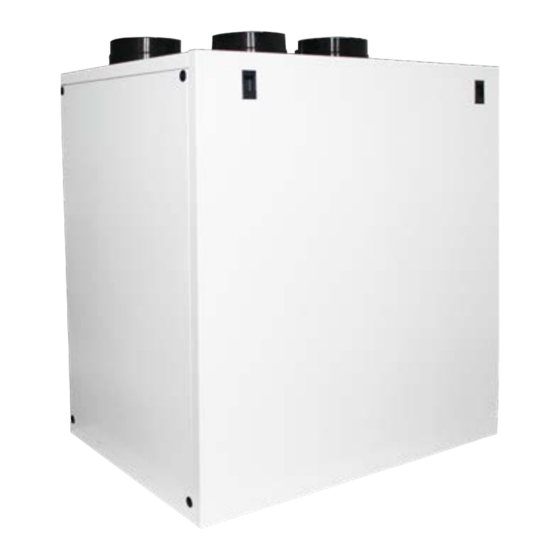
VIGO 550A
Mechanical Ventilation with
Heat & Coolth Recovery
Read this manual carefully before using the product and keep it in a
safe place for reference.
This product was constructed up to standard and in compliance with regulations
relating to electrical equipment and must be installed by technically qualified
personnel. The manufacturer assumes no responsibility for damage to persons or
property resulting from failure to observe the regulations contained in this booklet.
WARNING: Make sure that the mains supply to the unit is disconnected before performing any installation, service,
maintenance or electrical work!
WARNING: The installation and service of the unit and complete ventilation system must be performed by an
authorized installer and in accordance with local rules and regulations.
WARNING: If any abnormality in operation is detected, disconnect the device from the mains supply and contact a
qualified technician immediately.
Transport and storage
•
Do not leave the device exposed to atmospheric agents (rain, sun, snow, etc.).
•
Duct connections/duct ends must be covered during storage and installation.
Installation
•
After removing the product from its packaging, verify its conditions. Do not leave packaging within the reach of children or people with
disabilities.
•
Beware of sharp edges. Use protective gloves.
•
The device should not be used as an activator for water heaters, stoves, etc., nor should it discharge into hot air/fume vent ducts deriving
from any type of combustion unit or tumble dryer. It must expel air outside via its own special duct.
•
If the environment in which the product is installed also houses a fuel-operating device (water heater, methane stove etc., that is not a
"sealed chamber" type), it is essential to ensure adequate air intake, to ensure good combustion and proper equipment operation.
•
The electrical system to which the device is connected must comply with local regulations.
•
Before connecting the product to the power supply or the power outlet, ensure that:
-
the data plate (voltage and frequency) correspond to those of the electrical mains
-
the electrical power supply/socket is adequate for maximum device power.
•
For installation an omnipolar switch should be incorporated in the fixed wiring, in accordance with the wiring rules, to provide a full
disconnection under overvoltage category III conditions (contact opening distance equal to or greater than 3mm).
1.
Advertisement
Table of Contents

Summary of Contents for EG Homevent VIGO 550A
- Page 1 Installation & Maintenance Manual VIGO 550A Mechanical Ventilation with Heat & Coolth Recovery Read this manual carefully before using the product and keep it in a safe place for reference. This product was constructed up to standard and in compliance with regulations relating to electrical equipment and must be installed by technically qualified personnel.
-
Page 2: Product Information
• The device should not be used for applications other than those specified in this manual. • This appliance can be used by children aged from 8 years and above and persons with reduced physical, sensory or mental capabilities or lack of experience and knowledge if they have been given supervision or instruction concerning use of the appliance in a safe way and understand the hazards involved. -
Page 3: Dimensions And Weight
DIMENSIONS AND WEIGHT Ø155 Ø155 Ø155 Ø148 Ø148 Ø148 Weight (kg) Dimensions in mm. DUCT CONNECTIONS Connections from and to outside are set on the left side of the unit front view DEFAULT LEFT Connections from and to outside are set on the right side of the unit front view RIGHT The factory setting is LEFT. -
Page 4: Rating Label
RATING LABEL Fig.3.b Rating label TRANSPORT AND STORAGE WARNING: Make sure that specific warnings and cautions in Chapter 2 “Precautions” are carefully read, understood and applied! The appliance is delivered in one carton box. The appliance should be stored and transported in such a way that it is protected against physical damage that can harm spigots, casing, display etc... -
Page 5: Installation
INSTALLATION WARNING: Make sure that specific warnings and cautions in Chapter 2 “Precautions” are carefully read, understood and applied! This section describes how to install the unit correctly. The unit must be installed according to these instructions. Unpacking Verify that the unit (and eventual accessories) delivered is according to order before starting the installation. Any discrepancies from the ordered equipment must be reported to the supplier. - Page 6 Spirit level Spirit level Ø160mm Ø160mm H=min. 60mm 5.a Prepare the surface where the unit is to be mounted. Make sure that the surface is flat, levelled and that it supports the weight of the unit. Perform the installation in accordance with local rules and regulations. Use the wall fixing bracket as template to indicate where to drill the holes in the wall: make sure it is at spirit level.
- Page 7 PRECABLED ELECTRIC CONNECTIONS WARNING: Make sure that the mains supply to the unit is disconnected before performing any installation, service, maintenance or electrical work! WARNING: The installation and service of the unit and complete ventilation system must be performed by an authorized installer and in accordance with local rules and regulations.
- Page 8 ADDITIONAL ELECTRIC CONNECTIONS WARNING: Make sure that the mains supply to the unit is disconnected before performing any installation, service, maintenance or electrical work! WARNING: The installation and service of the unit and complete ventilation system must be performed by an authorized installer and in accordance with local rules and regulations.
- Page 9 COMMISSIONING Setting Fan speed The speed of the unit can be adjusted during installation according to required ventilation rate. Figure 6.a below shows performance curve at different settings of the 0-10V signal to the motors. Consumption refers to the 2 motors. Table 6.b indicates the efficiency of the heat exchanger and of the condensation produced in different climatic conditions, to help the installer or the designer of the ventilation system to decide if to connect one or both condensation drainages.
- Page 10 EXTERNAL INTERNAL 100m 200m 300m 400m 500m ƞ (%) ƞ (%) ƞ (%) ƞ (%) ƞ (%) T (°C) R.H. (%) T (°C) R.H. (%) (kg/h) (kg/h) (kg/h) (kg/h) (kg/h) 95.4 0.28 91.8 0.53 88.7 0.75 85.9 0.95 83.2 1.12 95.9 92.8 0.77...
- Page 11 Lw dB - SOUND POWER OCTAVE BAND Lp dB(A) Speed 100% Intake Supply Extract Exhaust Breakout Lw dB - SOUND POWER OCTAVE BAND Lp dB(A) Speed 80% Intake Supply Extract Exhaust Breakout Lw dB - SOUND POWER OCTAVE BAND Lp dB(A) Speed 60% Intake Supply...
-
Page 12: Operation
OPERATION WARNING: Make sure that specific warnings and cautions in Chapter 2 “Precautions” are carefully read, understood and applied! EXHAUST SUPPLY INTAKE EXTRACT LEFT ORIENTATION Intake air from outside Exhaust air to outside Supply air to inside Extract air from inside Fig. - Page 13 When powered on, the CTRL-DSP displays as follows: The speed (1-2-3) can be manually changed using or . Fig. 7.c CTRL-DSP operation screen User Menu on CTRL-DSP User Menu To enter the User Menu press OK or ESC. 1 Mode Selection To exit the User Menu press ESC or wait for about 60 seconds.
- Page 14 It allows to select the maximum speed (Boost). User Menu Press OK to select. 1 Mode Selection Choose NO or YES using or . Press OK to select and go back to the previous menu. 2 Boost Factory setting (DEFAULT): NO. 3 Boost Duration 4 Reset FILTER Alarm Boost speed can be adjusted during the installation.
- Page 15 It allows to set the time slots and the operating speeds throughout the week when the unit is set User Menu to Normal Mode 3V. 1 Mode Selection Press OK to select. 2 Boost Choose NO or YES using or . Press OK to select.
- Page 16 It allows to select one language among English, Italiano, Deutsch, Čeština, Slovenský, Français, Installer Menu Español, Nederlandse, 中国, Magyar and Русский. 1 Language Press OK to enter. 2 Date/time Select the language using or . 3 Machine orientation Press OK to select. Factory setting (DEFAULT): English.
- Page 17 It allows to set the Bypass operation parameters. Installer Menu Press OK to enter. 1 Language Select the submenu item using or and press OK to confirm: 2 Date/time 1 Desired Temperature: it is the ambient temperature desired by the user. 2 Tmax Free Heating: it is the maximum allowed outside temperature for free heating operation.
- Page 18 It allows to adjust the balancing of the two airflows. Installer Menu Press OK to enter. 8 Heating Select the submenu item using or : press OK to confirm. 10 Speed setting 1 Advanced Balancing 11 Airflow Balancing It allows to set the airflow balancing at speed 1-2-3-Boost, in supply and extract, only if the unit 12 F7 filter operates in Normal Mode 3V.
- Page 19 It allows to activate a short operation cycle of the fans at 100% speed for twice in a day. Installer Menu Press OK to enter. 15 Constant Pressure Choose NO or YES using or . 17 Periodic purge Factory setting (DEFAULT): NO. 18 Working Hours Counter If “YES”...
-
Page 20: Additional Functionalities
It allows to set the LCD contrast. Installer Menu Press OK to enter. 21 Load Settings Increase/decrease the contrast using or . 22 Restore Default Settings Press OK to confirm. 23 Contrast 24 Debug page It shows the internal functional parameters of the unit. Installer Menu Press OK to enter. -
Page 21: Maintenance And Service
MAINTENANCE & SERVICE WARNING: Make sure that specific warnings and cautions in Chapter 2 “Precautions” are carefully read, understood and applied! Maintenance can be carried out by the user. Service must be performed only by an authorized installer and in accordance with local rules and regulations. Questions regarding installation, use, maintenance and service of the unit should be answered by your installer or place of purchase! COMPONENTS LIST G4 FILTER... -
Page 22: Maintenance
MAINTENANCE WARNING: Make sure that the mains supply to the unit is disconnected before performing any installation, service, maintenance or electrical work! • Keep the unit surface free from dust. • Clean the filters with a vacuum cleaner following the below illustrations Fig. 8.b-c-d-e when the FILTER signal (Fig. 7.b - ) is displayed on LCD. - Page 23 • Clean the heat exchanger every year with a vacuum cleaner following the below illustrations Fig. 8.f-g-j. The actual need to perform this operation may vary depending on indoor and outdoor ambient conditions and on frequency of filter cleaning. • Clean the fans every year with a vacuum cleaner following the below illustrations Fig.
-
Page 24: Troubleshooting
TROUBLESHOOTING Fans do not start 1. Check that main supply gets to the unit. 2. Check that all connections are working (all connections in terminal box and fast couplings of intake and exhaust air fans). Reduced airflow 1. Check setting of fan speed on the CTRL-DSP (controller supplied). 2. -
Page 25: Warranty
ErP Directive - Regulations 1253/2014 - 1254/2014 Mark Homevent Model VIGO550A SEC class kWh/ c1) SEC warm climates -10,7 -6,7 kWh/ c2) SEC average climates -39,4 -34,4 kWh/ c3) SEC cold climates -77,4 -71,3 -66,1 Energy label Unit typology Residential - bidirectional Type of drive Variable speed drive Type of Heat Recovery System... - Page 26 NOTES...
- Page 27 NOTES...
- Page 28 Tel: +44 (0) 1384 275822, Email: sales@homevent.co.uk 46 Third Avenue, Pensnett Trading Estate, Kingswinford, West Midlands, DY6 7US, UK www.homevent.co.uk VIGO 550A . ISSUE A. 03.21...
Need help?
Do you have a question about the Homevent VIGO 550A and is the answer not in the manual?
Questions and answers