Table of Contents
Advertisement
This is a safety alert symbol and should never be ignored. When you see this symbol on labels or in
manuals, be alert to the potential for personal injury or death.
As with any mechanical equipment, personal injury can
result from contact with sharp sheet metal edges. Be
careful when you handle this equipment.
Unit Dimensions ............................................................2
Parts Arrangement.........................................................3
A96UH2E Gas Furnace .................................................4
Shipping and Packing List .............................................4
Safety Information .........................................................4
General ..........................................................................6
Combustion, Dilution & Ventilation Air ...........................7
Installation ...................................................................10
Filters ...........................................................................14
Duct System ................................................................14
Manufactured By
Allied Air Enterprises LLC
A Lennox International, Inc. Company
215 Metropolitan Drive
West Columbia, SC 29170
507581-04
INSTALLATION INSTRUCTIONS
A96UH2E
Warm Air Gas Furnace
Upflow/Horizontal Left Air Discharge
Direct Vent & Non-Direct Vent
This manual must be left with the homeowner for future reference.
CAUTION
Table of Contents
Save these instructions for future reference
Improper installation, adjustment, alteration, service
or maintenance can cause property damage, personal
injury or loss of life. Installation and service must be
performed by a licensed professional installer (or
equivalent), service agency or the gas supplier.
Venting.........................................................................16
Condensate Piping ......................................................33
Gas Piping ...................................................................37
Electrical ......................................................................40
Blower Performance ....................................................49
Unit Start-Up ................................................................52
Other Unit Adjustments................................................55
Service.........................................................................55
Planned Service ..........................................................57
Repair Parts List ..........................................................58
*P507581-04*
Issue 1933
WARNING
(P) 507581-04
Page 1 of 59
Advertisement
Table of Contents

Related Manuals for Armstrong A96UH2E

Summary of Contents for Armstrong A96UH2E
-
Page 1: Table Of Contents
Table of Contents Unit Dimensions ............2 Venting.................16 Parts Arrangement............3 Condensate Piping ............33 A96UH2E Gas Furnace ..........4 Gas Piping ..............37 Shipping and Packing List ..........4 Electrical ..............40 Safety Information ............4 Blower Performance ............49 General ................6 Unit Start-Up ..............52... -
Page 2: Unit Dimensions
Unit Dimensions 1 NOTE - 20 C/D (5 Ton) size units installed in upflow applications EXHAUST AIR 3−3/8 that require air volumes of 1800 cfm (850 L/s) or greater must OUTLET (86) have one of the following: Single side return air with transition, to accommodate 20 x 25 2 (51) x 1 in. -
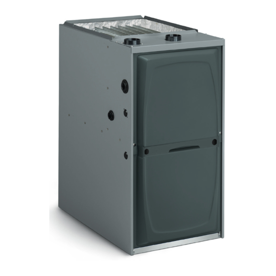
Page 3: Parts Arrangement
Parts Arrangement Figure 1. 507581-04 Issue 1933 Page 3 of 59... -
Page 4: A96Uh2E Gas Furnace
1 - Snap Plug in horizontal or upflow applications with bottom return air. 1 - Wire tie The A96UH2E can be installed as either a Direct Vent 1 - Condensate trap or a Non-Direct Vent Gas Central Furnace. Exception: A96UH2E030XE24B is direct vent only... - Page 5 Building Codes When installed, this furnace must be electrically grounded according to local codes. In addition, in the United States, In the USA, installation of gas furnaces must conform with installation must conform with the current National local building codes. In the absence of local codes, units Electric Code, ANSI/NFPA No.
-
Page 6: General
Use of Furnace as a Construction Heater NOTWITHSTANDING THE FOREGOING, INSTALLER IS RESPONSIBLE FOR CONFIRMING THAT THE USE Units may be used for heating of buildings or structures OF CONSTRUCTION HEAT IS CONSISTENT WITH under construction, if the following conditions are met to THE POLICIES AND CODES OF ALL REGULATING ensure proper operation. -
Page 7: Combustion, Dilution & Ventilation Air
of this information has been reprinted with permission from Combustion, Dilution & Ventilation Air the National Fuel Gas Code (ANSI-Z223.1/NFPA 54). This reprinted material is not the complete and official position If this unit is installed as a Non-Direct Vent Furnace, follow of ANSI on the referenced subject, which is represented the guidelines in this section. - Page 8 When the furnace is installed so that supply ducts carry a minimum free area of 1 square inch per 4,000 Btu (645 air circulated by the furnace to areas outside the space mm² per .59 kW) per hour of the total input rating of all containing the furnace, the return air must be handled by equipment in the enclosure (See Figure 6 and Figure 7).
- Page 9 Roof Terminated Exhaust Pipe Inlet Air (Minimum 12 in.(305mm) Ventilation Furnace Above crawl Louvers space floor) (Crawl space) Coupling or *Intake Debris Screen Provided) 3 in. to 2 in. Transition (Field Provided) Figure 8. Equipment in Confined Space - All Air from * See Maximum Vent Lengths table Outside NOTE-The inlet and outlet air openings shall each have a free area...
-
Page 10: Installation
Installation Units with 1/2 HP Blower Motor Setting Equipment WARNING Do not connect the return air ducts to the back of the furnace. Doing so will adversely affect the operation of Figure 11. the safety control devices, which could result in personal injury or death. - Page 11 Return Air Guidelines Return air can be brought in through the bottom or either WARNING side of the furnace installed in an upflow application. If the furnace is installed on a platform with bottom return, make Improper installation of the furnace can result in an airtight seal between the bottom of the furnace and the personal injury or death.
- Page 12 FURNACE FRONT 23 (584) IF BASE 3−1/4 Overall IS USED (83) (Maximum) Minimum WITHOUT 11 (279) IAQ CABINET, INDOOR AIR A SINGLE Maximum 22−7/16 QUALITY Unit side return air RETURN AIR 14 (356) (570) CABINET Opening PLENUM Overall MUST AIR FLOW (Maximum) COVER BOTH UNIT AND...
- Page 13 platform, as shown in Figure 20. A horizontal suspension Right-Hand Discharge kit (51W10) may be ordered from your distributor or use equivalent. Left End Right End NOTE: Heavy-gauge sheet metal straps may be used to Flow Flow suspend the unit from roof rafters or ceiling joists. When straps are used to suspend the unit in this way, support must be provided for both the ends.
-
Page 14: Filters
Return Air - Horizontal Applications Return air can be brought in through the bottom or either side of the furnace. If a furnace with bottom return air is Return air may be brought in only through the end of a installed on a platform, make an airtight seal between the furnace installed in the horizontal position. - Page 15 Piping and Fittings Specifications IMPORTANT Schedule 40 PVC (Pipe) D1785 A96UH2E exhaust and intake connections are made Schedule 40 PVC (Cellular Core Pipe) F891 of PVC. Use PVC primer and solvent cement when using PVC vent pipe. When using ABS vent pipe, use...
-
Page 16: Venting
STANDARD CONCENTRIC Outdoor Outdoor Flush 1-1/2" 2" 3" Exhaust Exhaust Mount Concentric Concentric Concentric Vent Pipe Accelerator Accelerator Model Dia. (Dia. X Length) (Dia. X Length) (in.) 71M80 69M29 60L46 1-1/2" x12" 2" x12" 51W11 +44W92++ +44W92++ 44W93+ 2-1/2" 2-1/2" 2-1/2"... - Page 17 WARNING CARBON MONOXIDE POISONING HAZARD Failure to follow the steps outlined below for each appliance connected to the venting system being placed into operation could result in carbon monoxide poisoning or death. The following steps shall be followed for each appliance connected to the venting system being placed into operation, while all other appliances connected to the venting system are not in operation:...
- Page 18 Regardless of the diameter of pipe used, the standard roof Use the following steps to correctly size vent pipe diameter. and wall terminations described in section Exhaust Piping Terminations should be used. Exhaust vent termination pipe is sized to optimize the velocity of the exhaust gas as 030, 045, it exits the termination.
- Page 19 Maximum Allowable Intake or Exhaust Vent Length in Feet Standard Termination at Elevation 0 - 4,500 ft 1-1/2” Pipe 2” Pipe 2-1/2" Pipe 3" Pipe Number Model Model Model Model of 90° Elbows Used Standard Termination at Elevation 4,501 - 10,000 ft 1-1/2”...
- Page 20 Maximum Allowable Intake or Exhaust Vent Length in Feet Concentric Termination at Elevation 0 - 4,500 ft 1-1/2” Pipe 2” Pipe 2-1/2" Pipe 3" Pipe Number Model Model Model Model of 90° Elbows Used Concentric Termination Elevation 4,501 - 10,000 ft 1-1/2”...
- Page 21 Maximum Allowable Exhaust Vent Lengths with Furnace Installed in a Closet or Basement Using Ventilated Attic or Crawl Space for Intake Air in Feet Standard Termination at Elevation 0 - 4,500 ft 1-1/2” Pipe 2” Pipe 2-1/2" Pipe 3" Pipe Number Model Model...
- Page 22 TYPICAL EXHAUST PIPE CONNECTIONS IN UPFLOW DIRECT OR NON-DIRECT VENT APPLICATIONS Pipe size determined in Table 5 2” 2” 2” 2” 3” 2” TRANSITION EXHAUST *2” 030/045/070 Only 1-1/2” DO NOT transition from smaller to larger TRANSITION pipe in horizontal runs 2”...
- Page 23 Intake Piping See Figure 27 through Figure 30 This gas furnace may be installed in either direct vent or non-direct vent applications. In non-direct vent applications, when intake air will be drawn into the furnace from the surrounding space, the indoor air quality must be considered and guidelines listed in the Combustion, Dilution &...
- Page 24 Use field-provided materials and the factory-provided TYPICAL AIR INTAKE PIPE CONNECTIONS air intake screen to route the intake piping as shown in UPFLOW NON-DIRECT VENT APPLICATIONS Figure 29 or Figure 30. Maintain a minimum clearance of 3” (76 mm) around the air intake opening. The air Intake Debris intake opening (with the protective screen) should...
- Page 25 Roof Terminated Exhaust Pipe Conditioned Space Inlet Air (Minimum Exhaust 12 in.(305mm) Ventilation Pipe Pipe Insulation Furnace Above crawl Louvers space floor) (Crawl space) Intake Conditioned Pipe Unconditioned Space Space Coupling or *Intake Debris Screen Provided) Figure 33. Insulating Exhaust Pipe in an 3 in.
- Page 26 In both Non–Direct Vent and Direct Vent applications, the vent termination is limited by local building codes. In the IMPORTANT absence of local codes, refer to the current National Fuel Gas Code ANSI Z223-1/NFPA 54 in U.S.A., and current Do not use screens or perforated metal in exhaust CSA-B149 Natural Gas and Propane Installation Codes in terminations.
- Page 27 VENT TERMINATION CLEARANCES FOR DIRECT VENT INSTALLATIONS IN THE USA AND CANADA INSIDE CORNER DETAIL Fixed Operable Fixed Closed Closed Operable AREA WHERE TERMINAL AIR SUPPLY INLET VENT TERMINAL IS NOT PERMITTED US Installations Canadian Installations Clearance above grade, veranda, 12 inches (305mm) or 12 in.
- Page 28 VENT TERMINATION CLEARANCES FOR DIRECT VENT INSTALLATIONS IN THE USA AND CANADA INSIDE CORNER DETAIL Fixed Operable Fixed Closed Closed Operable AREA WHERE TERMINAL AIR SUPPLY INLET VENT TERMINAL IS NOT PERMITTED US Installations Canadian Installations Clearance above grade, veranda, 12 inches (305mm) or 12 in.
- Page 29 On field supplied terminations, a minimum distance 3” (76MM) MIN. SIZE PER EXHAUST PIPE Inches (MM) between the end of the exhaust pipe and the end of TERMINATION SIZE the intake pipe without a termination elbow is 8” and a REDUCTION TABLE minimum distance of 6”...
- Page 30 FIELD FABRICATED WALL TERMINATION NOTE − FIELD−PROVIDED REDUCER MAY BE 2” (51mm) 3” (76mm) REQUIRED TO ADAPT LARGER VENT PIPE SIZE Vent Pipe Vent Pipe TO TERMINATION A− Minimum clearance above grade or average 12” (305 mm) 12” (305 mm) snow accumulation B−...
- Page 31 Details of Exhaust Piping Terminations for Non- DIRECT VENT CONCENTRIC WALL TERMINATION 71M80, 69M29 or 60L46 (US) Direct Vent Applications 44W92 or 44W93 (Canada) Exhaust pipes may be routed either horizontally through an outside wall or vertically through the roof. In attic or FIELD-PROVIDED REDUCER MAY BE REQUIRED TO closet installations, vertical termination through the roof...
- Page 32 Exhaust through Crawl Space Vent Option All 33” condensing gas furnaces (92%+) are now approved to be vented down through a crawl space. Ensure a vent pipe drain kit, 51W18 (USA) or 15Z70 (Canada), is used as directed through the floor joists and into the crawl space. SIZE TERMINATION See the following figures.
-
Page 33: Condensate Piping
24” max. Downflow Furnace Exhaust * Kit 51W18 is shown. Basement Floor To Termination KIT 51W18 (USA) KIT 15Z70 (Canada) 1/2” PVC to Code-Approved Drain NOTE: Upflow furnaces exhaust from the left side. All dimensions shown are typical for upflow or downflow furnaces. NOTE: All horizontal runs of exhaust pipe must slope back toward the kit a minimum of 1/4”... - Page 34 Install drain trap using appropriate PVC fittings, glue all joints. Glue the provided drain trap as shown in Figure 59. Route the condensate line to an open drain. Condensate line must maintain a 1/4” downward slope from the furnace to the drain. CAUTION Do not use copper tubing or existing copper condensate lines for drain line.
- Page 35 *Piping from furnace must slope down a minimum of 1/4” per ft. toward trap. Figure 55. Evaporator Coil Using a Common Drain (Unit shown in horizontal right hand discharge position) Figure 56. Condensate Trap with Optional Overflow Figure 57. Evaporator Coil Using a Common Drain Switch *Piping from furnace must slope down a minimum of 1/4”...
- Page 36 Optional Condensate Drain Connection Adapter 3/4 inch slip X 3/4 inch mpt (not furnished) 90° Street Elbow 3/4 inch PVC (not furnished) Adapter 3/4 inch slip X 3/4 inch mpt (not furnished) Condensate Drain Connection In Unit 1 (25 mm) Min. Vent 2 (50 mm) Max.
-
Page 37: Gas Piping
Gas Piping IMPORTANT Compounds used on threaded joints of gas piping must be resistant to the actions of liquified petroleum gases. CAUTION If a flexible gas connector is required or allowed by the authority that has jurisdiction, black iron pipe shall Leak Check be installed at the gas valve and extend outside the After gas piping is completed, carefully check all piping... - Page 38 Upflow Application Upflow Application Left Side Piping Right Side Piping (Standard) (Alternate) MANUAL MAIN SHUT-OFF VALVE MANUAL MAIN SHUT-OFF VALVE GROUND GROUND JOINT JOINT UNION UNION DRIP LEG Gas Valve Gas Valve FIELD PROVIDED AND INSTALLED DRIP LEG NOTE - BLACK IRON PIPE ONLY TO BE ROUTED INSIDE OF CABINET Figure 61.
- Page 39 Gas Pipe Capacity - FT³/HR (kL/HR) Nominal Length or Pipe - feet (m) Internal Iron Pipe Diameter Size - - inches inches (3.048) (6.096) (9.144) (12.192) (15.240) (18.288) (21.336) (24.384) (27.432) (30.480) (mm) (mm) .622 (12.7) (17.799) (4.96) (3.40) (2.75) (2.32) (2.07) (1.87)
-
Page 40: Electrical
Refer to Figure 66 for field wiring diagram and Electrical troubleshooting. The power supply wiring must meet Class I restrictions. ELECTROSTATIC DISCHARGE (ESD) Protected by either a fuse or circuit breaker, select circuit protection and wire size according to unit Precautions and Procedures nameplate. - Page 41 National Electrical Code ANSI/NFPA No. 70 (latest edition) continuous circulation speeds. and/or CSA C22.1 Electrical Code (latest edition) if an When the A96UH2E is running in the heating mode, external electrical source is utilized. the indoor blower will run on the ‘LOW HEAT” or “HIGH HEAT”...
- Page 42 3/16” QUICK CONNECT TERMINALS THERMOSTAT CONNECTIONS (TB1) FLAME SENSE SIGNAL DS = DEHUMIDIFICATION SIGNAL HI Cool 24VAC W2 = HEAT DEMAND FROM 2ND STAGE T/STAT HI HEAT 24VAC W1 = HEAT DEMAND FROM 1ST STAGE T/STAT LO COOL 24VAC R = CLASS 2 VOLTAGE TO THERMOSTAT LO HEAT 24VAC G = MANUAL FAN FROM THERMOSTAT C = THERMOSTAT SIGNAL GROUND CONNECTED TO...
- Page 43 Indoor Blower Operation DIP Switch Settings - Switches 3 and 4 -- Heating Mode Blower-Off Delay A96UH2E units are equipped with a two-stage integrated -- The blower-on delay of 30 seconds is not adjustable. control. This control manages ignition timing, heating...
- Page 44 Field Wiring Applications With Conventional Thermostat DIP Switch Settings and On-Board Links DIP Switch 1 On Board Links Must Be Cut To Select Thermostat Thermostat Wiring Connections System Options Heating Stages 1 Heat / 1 Cool FURNACE OUTDOOR T'STAT TERM. STRIP UNIT NOTE - Use DIP switch 2 to set...
- Page 45 Field Wiring Applications with Conventional Thermostat (Continued) DIP Switch Settings and On-Board Links DIP Switch 1 On Board Links Must Be Cut To Select Thermostat Thermostat Wiring Connections System Options Heating Stages 2 Heat / 2 Cool FURNACE OUTDOOR T'STAT TERM.
- Page 46 Field Wiring Applications with Conventional Thermostat (Continued) DIP Switch Settings and On-Board Links DIP Switch 1 Thermostat On Board Links Must Be Cut To Select Wiring Connections Thermostat Heating System Options Stages Dual Fuel L7724U FURNACE HEAT PUMP T'STAT TERM. STRIP Single Stage Heat Pump CUT ON-BOARD LINK...
- Page 47 Field Wiring Applications with Conventional Thermostat (Continued) DIP Switch Settings and On-Board Links DIP Switch 1 Wiring Connections Thermostat On Board Links Must Be Cut To Select Thermostat Heating System Options Stages Dual Fuel FURNACE L7742U HEAT PUMP TERM. STRIP T'STAT Single Stage Heat Pump...
- Page 48 Figure 66. Page 48 of 59 Issue 1933 507581-04...
-
Page 49: Blower Performance
Blower Performance A96UH2E030B08 Performance (Less Filter) External Air Volume / Watts at Various Blower Speeds Static High Medium-High Medium Medium-Low Pressure in. w.g. Watts Watts Watts Watts Watts 0.00 1025 0.10 0.20 0.30 0.40 0.50 0.60 0.70 0.80 A96UH2E045B12 Performance (Less Filter) External Air Volume / Watts at Various Blower Speeds Static... - Page 50 A96UH2E070B12 Performance (Less Filter) External Air Volume / Watts at Various Blower Speeds Static High Medium-High Medium Medium-Low Pressure in. w.g. Watts Watts Watts Watts Watts 0.00 1380 1305 1190 0.10 1360 1270 1180 0.20 1310 1250 1130 0.30 1275 1205 1100 0.40...
- Page 51 507581-04 Issue 1933 Page 51 of 59...
-
Page 52: Unit Start-Up
Allowable Heating Speeds Low Fire Heating Speeds High Fire Heating Speeds Model Yellow Blue Brown Black Yellow Blue Brown Black Factory Factory A96UH2E030B08S Allowed Allowed Allowed Allowed Allowed Setting Allowed Allowed Allowed Setting Factory Factory A96UH2E045B12S Allowed Allowed Allowed Allowed Setting Allowed Allowed... - Page 53 Turn OFF all electrical power to the unit. Turning Off Gas to Unit Set the thermostat to the lowest setting. This furnace is equipped with an ignition device which automatically lights the burners. Do not try to light the Turn off all electrical power to the unit if service is to burners by hand.
- Page 54 If flame is not detected after first ignition trial, the For proper furnace operation the minimum gas supply ignition control will repeat steps 3 and 4 four more pressure is 4.5” w.c and the maximum gas supply pressure times before locking out the gas valve. The ignition is 10.5”...
-
Page 55: Other Unit Adjustments
kit and pressure switch requirements at varying altitudes. Is pressure switch closed? Obstructed exhaust pipe The combustion air pressure switch is factory-set and will cause unit to shut off at pressure switch. Check requires no adjustment. termination for blockages. Obstructed pipe or termination may cause rollout switches to open. - Page 56 Electrical 15. Mark and remove wires from pressure switch. Remove pressure switch. Keep tubing attached to pressure Check all wiring for loose connections. switch. Check for the correct voltage at the furnace (furnace 16. Remove electrical junction box from the side of the operating).
-
Page 57: Planned Service
36. Reinstall electrical junction box. Disconnect and label wires from rollout switch. 37. Reinstall the combustion air inducer and flexible no Disconnect and label flame sensor wire. hub connector. Reconnect the 2 pin plug to the wire Disconnect and label ground wire from burner/manifold harness. -
Page 58: Repair Parts List
Repair Parts List The following repair parts are available through Allied Air dealers. When ordering parts, include the complete furnace model number listed on the CSA nameplate. All service must be performed by a licensed professional installer (or equivalent), service agency, or gas supplier. Cabinet Parts Heating Parts •... - Page 59 Requirements for Commonwealth of Massachusetts Modifications to NFPA-54, Chapter 10 INSPECTION. The state or local gas inspector of the side wall, horizontally vented, gas-fueled equipment Revise NFPA-54 section 10.8.3 to add the following shall not approve the installation unless, upon requirements: inspection, the inspector observes carbon monoxide For all side wall, horizontally vented, gas-fueled equipment...
Need help?
Do you have a question about the A96UH2E and is the answer not in the manual?
Questions and answers