Advertisement
Quick Links
Instruction Manual
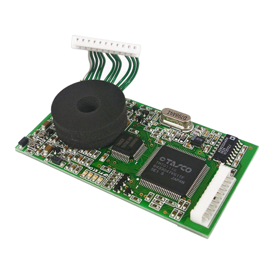
EJ-41U Terminal Node Controller Unit
Thank you for purchasing this fine Alinco product. This unit enables data communication when
it is properly installed in designated Alinco transceivers. Please read this manual, print the
contents if necessary, and keep this disk for future reference.
Since this device is capable of being used in commercial applications, some of the pages in this
manual are intentionally left blank to accommodate those uses in other regions.
Although we attempt to explain the features of this unit in a simple and comprehensive manner,
unless you have some knowledge about packet communications and APRS, you may have
difficulty understanding the contents of this manual. We apologize, but Alinco cannot provide
basic information of how packet and/or APRS works in general. Please consult your favorite
Ham radio stores for books on the subject and/or web-sites that support your area of interest
regarding those communication modes. You can explore the exciting world of data
communication by yourself, and we believe that this is a most interesting part of the king of
hobbies, Amateur Radio.
®
APRS
is a registered trademark of Bob Bruninga, WB4APR
Notice
• This unit should be used with ALINCO transceiver DR-135T/E.
• The memory of all settings of the unit are retained by the built-in lithium battery. If they go back to the
default, the battery might be consumed. In that case consult the dealer.
Accessories
The accessories listed below are included. Check that all of them are found before using.
• EJ-41U • 3.5ø stereo plug (for GPS input terminal) • Velcro for installation
• Instruction Manual • Instruction Manual DISK version
Installation
1) Remove the bottom case of DR-135.
2) Attach Velcro on the VCO case.
3) Unplug W1 of DSUB-9 connector from CN107 and plug it into
CN1 connector of EJ-41U.
4) Plug W2 of EJ-41U to the transceiver connector CN107.
5) Attach Velcro on EJ-41U so that it matches to the other Velcro on the
VCO case. (Be careful that the lithium battery doesn't mount
on the electric part.)
6) Install the bottom case after putting W1 neatly not to be caught in. (*1)
Advertisement

Related Manuals for Alinco EJ-S41U

Summary of Contents for Alinco EJ-S41U
- Page 1 Instruction Manual EJ-41U Terminal Node Controller Unit Thank you for purchasing this fine Alinco product. This unit enables data communication when it is properly installed in designated Alinco transceivers. Please read this manual, print the contents if necessary, and keep this disk for future reference.
- Page 2 GPS receiver and re-transmits it as a beacon at predetermined intervals. This advanced feature allows the easy setup of mobile units for GPS position-reporting systems such as APRS. Please refer the Alinco transceivers’ instruction manual for the installation of this unit.
- Page 3 2. Commands In this manual, unless otherwise specified, any “key” stands for the ones on the PC keyboard. The screen referred to is the PC monitor screen. 2-1 Command mode and Converse mode The typical operating modes of this unit are the Command mode and the Converse mode. It is necessary to use the command mode to set internal parameters in the EJ-41U.
- Page 4 2-4 Common commands for Amateur Radio Communication The following is a chart for the commands commonly used in Amateur Radio communications. Command Description reference AUTOLF Adds a line-feed [LF] after [CR] 3-3-6 AWLEN Specifies the data bits, 7 or 8, between the host and TNC 3-3-1 The transmission interval of the beacon signal in increments of 10 BEACON...
- Page 5 LOCATION Sets the transmission time of GPS data in 10 second increments. 5-6-4 LPATH Sets the outgoing path of GPS data. (Including DIGI-peater(s) used). 5-6-3 LTEXT The GPS data buffer. 5-6-6 Displays the LTEXT message as if it were received as a beacon signal 5-6-7 LTMON in preset intervals.
- Page 6 3-2 Caution on the communication buffer size 3-2-1 host to EJ-41U The temporary FIFO buffer, which pools serially received data, can only store 64 bites. Accordingly, when the software flow control is activated, if the host does not respond, the FIFO buffer will overflow.
- Page 7 3-3-3 Echo command Abbrev. E default ON range ON/OFF example ECHO OFF This is used to set the echo-back of characters input from the host. ON for echo-back, OFF for none. This is compatible to terminal software’s “local echo” setting. If this is not matched properly, the characters may be displayed twice or the characters may not be seen at all.
- Page 8 4-1 The basic TX/RX commands Check these commands if the unit does not transmit. 4-1-1 HBAUD command abbrev HB default 1200 parameter 1200/9600 example HBAUD 9600, HB1200 This is to determine the speed of transmitted data. If 1200 is set, it enables AFSK at 1200bps. At this position the modulated signal is output from the T1200(29 pin) on the gate-array but no output from the T9600 (35...
- Page 9 This command determines the Loop Back test status. When ON is selected, you may be able to monitor your transmitted messages on the screen, as it is processed in the gate-array. PTT signal is always off, so the signal won’t be transmitted. While the parameter is ON, you cannot monitor a received message, either.
- Page 10 (2) In this status, it waits until the slot time elapses, and generates a new random code again. (3) If the number is higher, it’s “blank” again. (4) Again, it’s waiting for another slot time. (5) This time the number is lower than the parameter. It’s a HIT and goes to transmit. If the other stations start transmitting, it stops counting the slot time, and generates code when the incoming signal is gone.
- Page 11 4-2-3 SLOTTIME command abbrev. SL default:3 parameter: 0 to 255 example: SL 5 This sets the time to generate a new random code for the P-Persistent CSMA system as previously described. It is set in 10 microsecond units. 4-2-4 DWAIT command abbrev.
- Page 12 In AX. 25 protocol, it detects the error on frames using CRC code. PASSALL command determines how to process such errors, if found. If it’s ON, the error frame is accepted. If OFF is selected only correct frames are accepted. Please leave this parameter OFF for error-free communication.
- Page 13 4-4-3 to 4-4-6 intentionally blanked (for commercial use only) 4-4-7 RESPTIME command abbrev: RES default: 5 parameter: 0-250 example: RES 5 In the connected packet mode, your TNC must reply to the destination by saying “Yes, I got your packet”(RR frame) after the information (I frame) is correctly received. Up to 7 RR frames can be sent together at one time.
- Page 14 4-4-10 TRIES command abbrev. TRI default: 0 parameter: 0-15 example: TRI 0 This is to display and adjust the current retry counter. If the command TRIES is entered, it might report back TRIES 9. You can enter TRIES 2 and in doing so, you reset the number of TRIES before reaching the cutoff figure set under RETRY.
- Page 15 4-5-1 intentionally blanked (engineers’ use only) 4-5-2 UNPROTO commands abbrev. U default: CQ parameter: destination’s callsign (with up to 8 with using VIA) example: U CQ U APRS V RELAY,WIDE This is used to determine destination’s callsign and relay stations. 4-5-3 BEACON command Abbrev.: B default: EVERY 0 parameter: EVERY/AFTER 0-250 Exapmle: B E 6...
- Page 16 4-6-2 CR command abbrev. CR default: ON parameter: ON/OFF example: CR ON This command determines if the [CR] code is added (or not) at the end of the I-frame transmission. [CR] is added if ON is chosen. [CR] won’t be added if OFF is chosen. Normally, the SENDPAC command does not include [CR] when it makes an I frame, as it is already “$0D”=[CR].
- Page 17 total of the frames should be less than 330 bites. This buffer size is the minimum required to send one maximum frame. The information field maximum length is 256 bites, but it becomes this size when other information such as destination callsign and relative relay station data is included.
- Page 18 l Pall / final-bite [P] pall bite ON [F] final-bite ON l Command/Response [C] command [R] Response l Sequences [Rn] Receiving sequences. n=0-7 [Sn] Transmitting sequence n=0-7 4-7-3 MCON command Abbrev. MC default OFF parameters: ON/OFF Example: MC ON This allows you to monitor frequency activity even when connected to another station. ON allows you to monitor while you are connected.
-
Page 19: Gps Connection
5. GPS CONNECTION 5-1 Using a GPS Receiver with the EJ-41U GPS, the Global Positioning System, transmits signals from a constellation of GPS satellites orbiting the earth. A GPS receiver uses data from these satellites to determine the current geographical position of the receiver. This system is widely used in navigation today. The EJ-41U can transmit the position data taken from the GPS receiver at pre-determined intervals. - Page 20 5-4 The meaning of GPS information (The data that can be analyzed and re-structured) The EJ-41U analyzes data received from the GPS receiver. Then, based on that data, it converts from one format to another. When the initial part of the input data and the GPSTEXT command matches, it re-transmits that data as a LTEXT beacon.
- Page 21 : The status of the internal oscillator of the GPS receiver. : not related to the user. : DMS/DMD identifier. Letters for DMS, numbers for DMD. : Parity. [0] for o, [E] for 1. <CR><LF> end of the data 5-4-2 SMATC This format is used for SONY’s car-navigation system “Columbus”.
- Page 22 *$GPVTG: starts GPVTG sentence l True course direction in degree related to the North. l T fixed, means True Course l Magnetic course direction in degree. l M fixed, means Magnetic course l Speed in knots=1.852Km/h. l N fixed, means Knots. l Ground speed in Km/h l K fixed, means ground speed unit in Km l *hh<CR><LF>...
- Page 23 l Hh<CR><LF> the check-sum and the end of the message. 5-4-7 $PNTS This is a private-sentence based on NMEA-0183. The data contains date, time, latitude, longitude, moving speed, direction, altitude plus a short message, group codes, and icon numbers. The EJ-41U does not analyze this format but can re-structure it. The data contains the following information: l $PNTS Starts the $PNTS sentence l version...
- Page 24 5-5 GPS information processing detail In the EJ-41U, data in the LTXT buffer will be sent out as a beacon. Other than user entered data placed in the buffer by using the LTXT command, LTXT can be updated automatically with new data received from the GPS receiver.
- Page 25 5-6-2 Intentionally left blank 5-6-3: LPATH command abbrev: LPATH default: GPS parameter: destination’s callsign (may be combined with V for relay up to 8 stations) example: LPA GPS VIA RELAY,WIDE This is an UNPROTO compatible command used for GPS beacon transmissions. Set the receiving stations’...
- Page 26 With this parameter ON, it outputs all information just as other beacons are received however SET THIS PARAMETER OFF FOR APRS use; otherwise the position of your station may not be read. 5-6-9 GPSTEXT command Abbrev. GPST default: $PNTS parameter: up to 6 letters Example: GPST $GPRMC When the initial part of the input data received by GPS port and the GPSTEXT command match, the GPS input data contained in the string will be automatically placed in the LTEXT buffer.
- Page 27 This command transmits the entered characters to the GPS port. This command is used to send initializing command(s) to the GPS. The content cannot be stored in memory but some GPS units will have a memory feature (This is mainly to conserve space in the RAM which is very limited in this unit).
- Page 28 Chapter 7/8 Intentionally left blank. Chapter 9 Miscellaneous commands The followings are miscellaneous commands: l Restart and Reset commands l Display commands l Display setting according to the terminal software 9-1 Restart and Reset 9-1-1 RESTART command Abbrev. RESTART default : none parameter: none Example: RESTART This will restart the TNC.
- Page 29 9-3 Display setting according to the terminal software 9-3-1 BBSMSGS command Abbrev. BBS default: OFF parameter: ON/OFF Example: BBS OFF This is to select how to output messages from the TNC. If ON is selected, the CR code is added before the message such as “*** disconnected”...
Need help?
Do you have a question about the EJ-S41U and is the answer not in the manual?
Questions and answers