Table of Contents
Advertisement
Quick Links
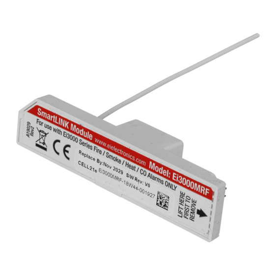
Ei3000MRF
SmartLINK Module
Instruction Manual
Read and retain carefully for as long as the product is being used. It contains vital
information on the operation and installation of your Alarm. The leaflet should be
regarded as part of the product.
If you are just installing the unit, the leaflet MUST be given to the householder. The
leaflet is to be given to any subsequent user.
Advertisement
Table of Contents

Summary of Contents for Aico SmartLINK Ei3000MRF
- Page 1 Ei3000MRF SmartLINK Module Instruction Manual Read and retain carefully for as long as the product is being used. It contains vital information on the operation and installation of your Alarm. The leaflet should be regarded as part of the product. If you are just installing the unit, the leaflet MUST be given to the householder.
-
Page 3: Table Of Contents
Table of Contents page Introduction ................Installation and House Coding ........... Additional Features ..............Indicator Summary ..............System Examples ............... Testing the system ..............Interconnected Carbon Monoxide Alarms and Smoke Alarms ... SmartLINK Troubleshooting ............Technical Specifications ............. Guarantee .................. Limitations of Radio Communications ........ -
Page 4: Introduction
Introduction The Ei3000MRF SmartLINK Module is the next generation RF module designed to fit in the Ei160e and Ei2110e series, Easi-fit mains powered Alarms. The Ei3000MRF RadioLINK Module effectively replaces the Ei168RC RadioLINK Base. The primary function of the Ei3000MRF is to wirelessly interconnect all Ei Electronics Alarms in a system by the means of an RF signal i.e. -
Page 5: Installation And House Coding
Installation and House Coding N.B Disconnect Mains Before Alarm Head Removal After disconnecting the mains power supply, it is now safe to remove the Alarm from its base. Using a screwdriver, insert into the removal slot on the side of the Alarm. Push the lower half of the Alarm away from the screwdriver, in the direction of the arrow on the cover (see Figure 1 below). - Page 6 Fitting the Ei3000MRF Module To fit the Ei3000MRF Module, first hold the flexible antenna and guide it into its designated hole in the rear of the unit until about 2/3 of its length is inserted (Fig. 2a). Then, hold the module housing (Fig. 2b) & plug it into the Alarm, being careful to align the pins and keeping them perpendicular to the base as the module is inserted (Fig.
- Page 7 House Coding the Unit Ensure that the Alarm is re-connected to the base correctly by checking for the green LED on the cover of the Alarm. Power supply to the Ei3000MRF will be confirmed by an initial flash of the red, blue and green LED on the side of the unit (see Fig 3).
- Page 8 blue, red & green LED Figure 3 Figure 4...
- Page 9 The Alarm will now send a signal to all the other RF devices in the system to exit House Code. Alternatively, the RF Alarms will automatically exit the House Code mode after 30 minutes. To check the system, press the test button on any Alarm. After a few seconds all Alarms should now sound.
- Page 10 Figure 5b Figure 5c...
-
Page 11: Additional Features
Additional Features The Ei3000MRF SmartLINK Module provides additional features not available with Ei Electronics RadioLINK products. The following features will only work with SmartLINK devices. 1. Remote House Coding (required if you want to add an Alarm to an installed system) 2. - Page 12 2. Monitoring The Ei3000MRF SmartLINK Module has the ability to “Monitor” the RF signal path and strength. This is an enhanced self-monitoring function that recognises system tampering or alarm head removal. In monitoring mode each Alarm will check the presence of its strongest received RF signal. If the signal is missing then the Alarm will record a monitoring failure event.
-
Page 13: Indicator Summary
Ei100MRF Indicator Summary Normal Operation Blue LED Red LED Green LED Sounder Power Up 1 flash 1 flash 1 flash Standby Alarm 3.5 Sec flash followed by flash every 10 Sec Full Sound Head Removal 3.5 Sec flash every 6 mins for 4 hrs Mode-Enter / Exit Button Action Blue LED... -
Page 14: System Examples
System Examples RF System (RadioLINK & RadioLINK + ) RadioLINK RadioLINK Smoke Alarm Smoke Alarm RadioLINK RadioLINK Heat Alarm Smoke Alarm RF Tool RadioLINK + Smoke Alarm Data Extraction RadioLINK + Heat Alarm Note: Remote House Coding / Monitoring / Data Extraction only available on RadioLINK + Alarms... - Page 15 RadioLINK + & Hardwired Hybrid System RadioLINK + RadioLINK + Hardwired Hardwired Hardwired Ei2110e Smoke Alarm Heat Alarm Smoke Alarm Smoke Alarm MultiSensor Alarm * RF Tool Data Extraction * N.B. In Hybrid systems we recommend up to 6 Alarms on the hard-wire interconnection line and the link Alarm be an Ei2110e MultiSensor Alarm...
-
Page 16: Testing The System
Testing the System Check that the green light is on continuously to indicate that mains power is present and that the red light flashes every 40 seconds. Frequent testing of the system is a requirement to ensure its continued and safe operation. Guidelines and best practices for testing are as follows: 1. -
Page 17: Interconnected Carbon Monoxide Alarms And Smoke Alarms
The local Alarm will stop sounding but you will hear the other Alarms still sounding in the distance. End of Life (EOL) Check Check the ‘replace by date’ label on all Ei3000MRF modules and attached Alarms. If the date has been exceeded then the module should be replaced. Interconnected Carbon Monoxide Alarms and Smoke Alarms Identifying source of Alarm... -
Page 18: Smartlink Troubleshooting
SmartLINK Troubleshooting It is important that all Alarms in your system communicate with each other. The number of walls, ceilings and metal objects in the signal path will reduce the strength of the SmartLINK signals between the Alarms. Accordingly, one or more Smoke/Heat/CO Alarms may have difficulties in communicating to all the other Alarms in the system. -
Page 19: Technical Specifications
Technical Specifications Supply Voltage: 9V from attached alarm RF Range: A minimum of 100 metres in free space RF Visual Indicator: Blue light flashes continuously for 0.5 to 3.5 seconds while transmitting RF signal RF Frequency: 868.499MHz (1% duty cycle) Max RF Power: +10dBm Dimensions:... -
Page 20: Guarantee
Guarantee Ei Electronics guarantees this RF SmartLINK Module for five years from date of purchase against any defects that are due to faulty materials or workmanship. This guarantee only applies to normal conditions of use and service, and does not include damage resulting from accident, neglect, misuse, unauthorised dismantling, or contamination howsoever caused. - Page 21 is to determine whether there are sources of interference preventing communication, that the radio paths have not been disrupted by moving furniture or renovations, and if so, to give a warning of these and other faults. 0889 Hereby, Ei Electronics declares that this Ei3000MRF SmartLINK Module is in compliance with the essential requirements and other relevant provisions of Directive 1999/5/EC.
- Page 22 Block E1 The crossed out wheelie bin symbol that is on your product indicates that this product should not be disposed of via the normal household waste stream. Proper disposal will prevent possible harm to the environment or to human health. When disposing of this product please separate it from other waste streams to ensure that it can be recycled in an environmentally sound manner.
- Page 24 Aico Ltd. Mile End Business Park, Maesbury Rd, Oswestry, Shropshire SY10 8NN, U.K. Tel: 01691 664100 www.aico.co.uk Ei Electronics. Shannon, Co Clare, Ireland. Tel:+353 (0)61 471277 www.eielectronics.com P/N B19140 Rev0 © Ei Electronics 2017...
Need help?
Do you have a question about the SmartLINK Ei3000MRF and is the answer not in the manual?
Questions and answers