Table of Contents
Advertisement
Quick Links
Advertisement
Table of Contents

Related Manuals for Elk Products EZ8 ELK-M1EZ8

Summary of Contents for Elk Products EZ8 ELK-M1EZ8
- Page 1 INSTALLATION MANUAL Cross Platform Control Part # ELK-M1EZ8 A member of the M1 Family Specifications, Installation and Programming M1 includes the SIA CP-01 Standards for False Alarm Reduction † L523 Rev. I 08/06/08 Current with Firmware 4.5.4...
- Page 2 Introduction LIMITATION This Control is designed to warn against unauthorized entry and other situations. However, it is not a guarantee of protection against the occurrence of burglary, fire, or other emergency. Any alarm system is subject to compromise or failure to warn for various reasons. For example: - Unauthorized access can be gained through unprotected points or by disarming or bypassing protected points.
-
Page 3: Table Of Contents
Table of Contents Specifications, Features, and Benefits ..................... 4 Wiring & Hookup Diagram ........................... 5 Section 1 - Installation and Wiring ......................7 1.1 Planning the Installation ........................7 1.2 Parts Diagram & Descriptions ......................7 1.3 Mounting and Wiring Preparation ....................... 7 1.4 Control Wiring ............................ -
Page 4: Specifications, Features, And Benefits
Specifications, Features, and Benefits • Total number of Rules Supported: 528 General: • Large zone capacity: 8 on-board zones expandable to 200 • Rules utilize easy to understand text based references • Wireless capability: Up to 48 zones • Control lighting using RS-232 serial or 2-way Power Line †... -
Page 5: Wiring & Hookup Diagram
Wiring & Hookup Diagram Sealed Lead Acid Battery (ELK-1250) 12Volt - 5Ah min. See UL requirements for sizes and standby This unit provides Residential fire alarm service when installed according to Battery Power LED is ON when AC is present. times. - Page 6 Intentionally Left Blank Page 6 M1EZ8 Installation and Programming...
-
Page 7: Section 1 - Installation And Wiring
Section 1 - Installation and Wiring 1.1 Planning the Installation The first step in any multi-zone security system installation is planning the job. Read this entire manual to familiarize yourself with all system features and procedures before actually beginning the installation. -
Page 8: Control Wiring
Hookup Diagram for Keypad Splice 6 Pin Keypad Wiring Assembly to the Data Bus cable using ELK-900-2 "B" Connectors. See Note about ELK-M1KP Data Bus Keypad Termination Wiring Keypad 1 BLACK Data Bus Cable Assembly WHITE CAT5 or CAT6 Recommended GREEN The optional Zone Input # or Output # is BLUE... - Page 9 Two-Wire Smoke Zone (Zone 8) To enable use of two-wire smoke detectors position Jumper JP1 to the 2 wire smoke position. Go to Installer programming mode, Menu 05 - Zone Definitions, and program Zone 8 as a Fire zone (Def=10). Step to next location and program Wire Type=6.
- Page 10 AC Failure, Low Battery, and Automatic Low Voltage Shutdown During an AC power failure the battery automatically takes over and AC Fail trouble annunciates at the keypad. The communicator can be programmed to report AC Fail to the Central Station after a time delay (see Menu 12, System Option 01). If the battery voltage falls below 11.2 VDC a Low Battery Trouble condition will occur.
-
Page 11: Data Bus E.o.l. Termination - Very Important
Data Bus E.O.L. Termination - VERY IMPORTANT! The control features a true RS-485 “differential” data bus operating at 38,400 bits per second. This is relatively high speed by industry standards and ensures fast, accurate communications. With this speed, EOL data bus terminating resistors are required to eliminate the possibility of reflection errors caused by varying cable lengths. - Page 12 The ELK-M1DBHR † "Active" Data Bus Hub Retrofit splits the Controls' main RS-485 Data Bus into 4 managed RS-485 branches. Each branch can have 2 parallel home run cables for a total of 8 home runs. The last (end of line) device on each home run should be jumper terminated to insure proper operation and supervision.
-
Page 13: Section 2 - Operating The System
Section 2 - Operating the System 2.1 Introduction The control has factory default programming which make it easy to bench test prior to installation. Terminate all zones with EOL resistors, then connect a keypad, transformer, and battery. The factory (Master) user code is 3456. This code can operate all user related features of the system. -
Page 14: Keypad Overview
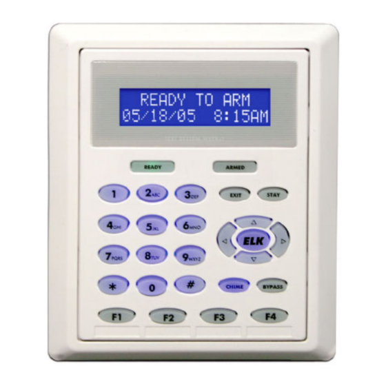
2.5 Keypad Overview Ready Light - ON when all burglar zones are secure and the system is OK to arm. If OFF, one or more zones are violated (not secure). For maximum security, secure all zones before arming the system. If FLASHING, one or more force-armable zones are violated. Force arming temporarily excludes violated zone(s) from the system. -
Page 15: Keypad Menus
Keypad Menus 1 2 3 4 5 6 7 8 9 0 1 2 3 4 5 6 7 8 9 0 1 2 3 4 5 6 7 8 9 0 1 2 3 4 5 6 7 8 9 0 1 2 3 4 5 6 7 8 9 0 1 2 3 4 5 6 7 8 9 0 The control offers extended Menu Options via the center navigation “ELK”... - Page 16 1 2 3 4 5 6 7 8 9 0 1 2 3 4 5 6 7 8 9 0 1 2 3 4 5 6 7 8 9 0 1 2 3 4 5 6 7 8 9 0 1 2 3 4 5 6 7 8 9 0 1 2 3 4 5 6 7 8 9 0 Menu 3 permits a local walk test of all zones assigned to this keypad’s area.
- Page 17 1 2 3 4 5 6 7 8 9 0 1 2 3 4 5 6 7 8 9 0 1 2 3 4 5 6 7 8 9 0 To perform system tests press the right arrow key. Then press the up or down arrow keys to 1 2 3 4 5 6 7 8 9 0 1 2 3 4 5 6 7 8 9 0 1 2 3 4 5 6 7 8 9 0 1 2 3 4 5 6 7 8 9 0 1 2 3 4 5 6 7 8 9 0 1 2 3 4 5 6 7 8 9 0 84-System...
-
Page 18: Menu 0 - Select Keypad Alternate Area - Multi-Area (Partition) Operation
1 2 3 4 5 6 7 8 9 0 1 2 3 4 5 6 7 8 9 0 1 2 3 4 5 6 7 8 9 0 1 2 3 4 5 6 7 8 9 0 1 2 3 4 5 6 7 8 9 0 1 2 3 4 5 6 7 8 9 0 1 2 3 4 5 6 7 8 9 0 1 2 3 4 5 6 7 8 9 0 1 2 3 4 5 6 7 8 9 0 From this menu you may press the RIGHT arrow to enter Installation Level Programming. -
Page 19: Section 3 - Programming The Control
Section 3 - Programming The Control 3.1 Introduction The Security functionality of the Control can be programmed either from an ELK-M1KP LCD Keypad, ELK-M1KP2 LCD Keypad, OR from the ELK-RP PC Software. The keypad features a menu-driven “Text” based interface with simple Yes/No answers for most options. -
Page 20: Communicator Setup Checklist
3.5 Communicator Setup Checklist The Communicator (Dialer) can dial up to 8 phone numbers plus RP. Digital reporting formats include: Pulse 4+2, SIA, Contact ID, and Pager. Use the following checklist for each required telephone number. Under Menu 08 - Telephone Account Setup, select one of the telephone numbers and program the following: Option 01: Select the desired reporting format - 0=Disable, 1=Contact ID, 2=SIA, 3=Pulse 4+2, 4=Pager Option 02: Set the priority for the first (primary number) to 0 = Always Report. - Page 21 Page 21 M1EZ8 Installation and Programming...
-
Page 22: Menu 01 - Bus Module Enrollment
Menu 01 - Bus Module Enrollment 1 2 3 4 5 6 7 8 9 0 1 2 3 4 5 6 7 8 9 0 1 2 3 4 5 6 7 8 9 0 1 2 1 2 3 1 2 3 4 5 6 7 8 9 0 1 2 3 4 5 6 7 8 9 0 1 2 3 4 5 6 7 8 9 0 1 2 1 2 3 Press RIGHT arrow key to select this menu. -
Page 23: Menu 02 - User Code Options
Menu 02 - User Code Options 1 2 3 4 5 6 7 8 9 0 1 2 3 4 5 6 7 8 9 0 1 2 3 4 5 6 7 8 9 0 1 2 1 2 3 1 2 3 4 5 6 7 8 9 0 1 2 3 4 5 6 7 8 9 0 1 2 3 4 5 6 7 8 9 0 1 2 1 2 3 Press RIGHT arrow key to select this menu. -
Page 24: Menu 03 - Area Definitions
Menu 03 - Area Definitions 1 2 3 4 5 6 7 8 9 0 1 2 3 4 5 6 7 8 9 0 1 2 3 4 5 6 7 8 9 0 1 2 1 2 3 1 2 3 4 5 6 7 8 9 0 1 2 3 4 5 6 7 8 9 0 1 2 3 4 5 6 7 8 9 0 1 2 1 2 3 Press RIGHT arrow key to select this menu. - Page 25 Menu 03 - Area Definitions (continued) Area Definitions Description of Option 1 2 3 4 5 6 7 8 9 0 1 2 3 4 5 6 7 8 9 0 1 2 3 4 5 6 7 8 9 0 1 2 1 2 3 1 2 3 4 5 6 7 8 9 0 1 2 3 4 5 6 7 8 9 0 1 2 3 4 5 6 7 8 9 0 1 2 1 2 3 If Yes, a Closing Ringback signal (otherwise known as closing report successful) will be 1 2 3 4 5 6 7 8 9 0 1 2 3 4 5 6 7 8 9 0 1 2 3 4 5 6 7 8 9 0 1 2 1 2 3...
-
Page 26: Menu 04 - Keypad Definitions
Menu 04 - Keypad Definitions 1 2 3 4 5 6 7 8 9 0 1 2 3 4 5 6 7 8 9 0 1 2 3 4 5 6 7 8 9 0 1 2 1 2 3 1 2 3 4 5 6 7 8 9 0 1 2 3 4 5 6 7 8 9 0 1 2 3 4 5 6 7 8 9 0 1 2 1 2 3 Press RIGHT arrow key to select this menu. - Page 27 Menu 04 - Keypad Definitions (continued) Keypad Definitions Description of Option 1 2 3 4 5 6 7 8 9 0 1 2 3 4 5 6 7 8 9 0 1 2 3 4 5 6 7 8 9 0 1 2 1 2 3 1 2 3 4 5 6 7 8 9 0 1 2 3 4 5 6 7 8 9 0 1 2 3 4 5 6 7 8 9 0 1 2 1 2 3 To program the F1 key definitions press the right arrow key.
-
Page 28: Menu 05 - Zone Definitions
Menu 05 - Zone Definitions 1 2 3 4 5 6 7 8 9 0 1 2 3 4 5 6 7 8 9 0 1 2 3 4 5 6 7 8 9 0 1 2 1 2 3 1 2 3 4 5 6 7 8 9 0 1 2 3 4 5 6 7 8 9 0 1 2 3 4 5 6 7 8 9 0 1 2 1 2 3 Press RIGHT arrow key to select this menu. - Page 29 Menu 05 - Zone Definitions (continued) Def Zone Description Operating Characteristics 15 † Keyfob - Used when a wireless keyfob is enrolled into a receiver at this zone ID location. 16 Non Alarm - Intended for use in Whenever/And/Then rules from the Remote Programming RP software. This zone type DOES NOT ACTIVATE any alarm and is not logged in the Event log.
- Page 30 Menu 05 - Zone Definitions (continued) Zone Definitions Description of Option 1 2 3 4 5 6 7 8 9 0 1 2 3 4 5 6 7 8 9 0 1 2 3 4 5 6 7 8 9 0 1 2 1 2 3 4 Dialer delay is designed to reduce false alarm dispatches.
-
Page 31: Menu 06 - Alarm Duration Timers
Menu 06 - Alarm Duration Timers 1 2 3 4 5 6 7 8 9 0 1 2 3 4 5 6 7 8 9 0 1 2 3 4 5 6 7 8 9 0 1 2 1 2 3 1 2 3 4 5 6 7 8 9 0 1 2 3 4 5 6 7 8 9 0 1 2 3 4 5 6 7 8 9 0 1 2 1 2 3 Press RIGHT arrow key to select this menu. -
Page 32: Menu 07 - Global System Definitions
Menu 07 - Global System Definitions 1 2 3 4 5 6 7 8 9 0 1 2 3 4 5 6 7 8 9 0 1 2 3 4 5 6 7 8 9 0 1 2 1 2 3 1 2 3 4 5 6 7 8 9 0 1 2 3 4 5 6 7 8 9 0 1 2 3 4 5 6 7 8 9 0 1 2 1 2 3 Press RIGHT arrow key to select this menu. - Page 33 Menu 07 - Global System Definitions (continued) Global Sys Definitions Description of Option 1 2 3 4 5 6 7 8 9 0 1 2 3 4 5 6 7 8 9 0 1 2 3 4 5 6 7 8 9 0 1 2 1 2 3 1 2 3 4 5 6 7 8 9 0 1 2 3 4 5 6 7 8 9 0 1 2 3 4 5 6 7 8 9 0 1 2 1 2 3 Any of the Areas 2 thru 8 may be made common to Area 1.
- Page 34 Menu 07 - Global System Definitions (continued) Global Sys Definitions Description of Option 1 2 3 4 5 6 7 8 9 0 1 2 3 4 5 6 7 8 9 0 1 2 3 4 5 6 7 8 9 0 1 2 1 2 3 4 1 2 3 4 5 6 7 8 9 0 1 2 3 4 5 6 7 8 9 0 1 2 3 4 5 6 7 8 9 0 1 2 1 2 3 4 †...
- Page 35 Menu 07 - Global System Definitions (continued) Global Sys Def Description of Option 1 2 3 4 5 6 7 8 9 0 1 2 3 4 5 6 7 8 9 0 1 2 3 4 5 6 7 8 9 0 1 2 1 2 3 1 2 3 4 5 6 7 8 9 0 1 2 3 4 5 6 7 8 9 0 1 2 3 4 5 6 7 8 9 0 1 2 1 2 3 †...
-
Page 36: Menu 08 - Telephone Account Setup
Menu 08 - Telephone Account Setup 1 2 3 4 5 6 7 8 9 0 1 2 3 4 5 6 7 8 9 0 1 2 3 4 5 6 7 8 9 0 1 2 1 2 3 1 2 3 4 5 6 7 8 9 0 1 2 3 4 5 6 7 8 9 0 1 2 3 4 5 6 7 8 9 0 1 2 1 2 3 Press RIGHT arrow key to select this menu. - Page 37 Menu 08 Telephone Account Setup (continued) Telephone Acct Setup Description of Option 1 2 3 4 5 6 7 8 9 0 1 2 3 4 5 6 7 8 9 0 1 2 3 4 5 6 7 8 9 0 1 2 1 2 3 1 2 3 4 5 6 7 8 9 0 1 2 3 4 5 6 7 8 9 0 1 2 3 4 5 6 7 8 9 0 1 2 1 2 3 The Account number for Area 4 (up to 6 digits) when it is reported to this telephone 1 2 3 4 5 6 7 8 9 0 1 2 3 4 5 6 7 8 9 0 1 2 3 4 5 6 7 8 9 0 1 2 1 2 3...
-
Page 38: Menu 09 - Area Reporting Codes
Menu 09 - Area Reporting Codes 1 2 3 4 5 6 7 8 9 0 1 2 3 4 5 6 7 8 9 0 1 2 3 4 5 6 7 8 9 0 1 2 1 2 3 1 2 3 4 5 6 7 8 9 0 1 2 3 4 5 6 7 8 9 0 1 2 3 4 5 6 7 8 9 0 1 2 1 2 3 Press RIGHT arrow key to select this menu. - Page 39 Menu 09 - Area Reporting Codes (continued) Area Report Codes Description of Option 1 2 3 4 5 6 7 8 9 0 1 2 3 4 5 6 7 8 9 0 1 2 3 4 5 6 7 8 9 0 1 2 1 2 3 1 2 3 4 5 6 7 8 9 0 1 2 3 4 5 6 7 8 9 0 1 2 3 4 5 6 7 8 9 0 1 2 1 2 3 Duress code will be reported if the area is armed or disarmed by a valid user code that is 1 2 3 4 5 6 7 8 9 0 1 2 3 4 5 6 7 8 9 0 1 2 3 4 5 6 7 8 9 0 1 2 1 2 3...
-
Page 40: Menu 10 - Zone Reporting Codes
Menu 10 - Zone Reporting Codes 1 2 3 4 5 6 7 8 9 0 1 2 3 4 5 6 7 8 9 0 1 2 3 4 5 6 7 8 9 0 1 2 1 2 3 1 2 3 4 5 6 7 8 9 0 1 2 3 4 5 6 7 8 9 0 1 2 3 4 5 6 7 8 9 0 1 2 1 2 3 Press RIGHT arrow key to select this menu. -
Page 41: Menu 11 - Keypad F-Key Reporting Codes
Menu 11 - Keypad F-Key Reporting Codes 1 2 3 4 5 6 7 8 9 0 1 2 3 4 5 6 7 8 9 0 1 2 3 4 5 6 7 8 9 0 1 2 1 2 3 1 2 3 4 5 6 7 8 9 0 1 2 3 4 5 6 7 8 9 0 1 2 3 4 5 6 7 8 9 0 1 2 1 2 3 Press RIGHT arrow key to select this menu. -
Page 42: Menu 12 - Sys Report Code Options & Codes
Menu 12 - Sys Report Code Options & Codes 1 2 3 4 5 6 7 8 9 0 1 2 3 4 5 6 7 8 9 0 1 2 3 4 5 6 7 8 9 0 1 2 1 2 3 1 2 3 4 5 6 7 8 9 0 1 2 3 4 5 6 7 8 9 0 1 2 3 4 5 6 7 8 9 0 1 2 1 2 3 Press RIGHT arrow key to select this menu. - Page 43 Menu 12 - Sys Report Code Options & Codes (continued) Sys Rpt Code Options Description of Option 1 2 3 4 5 6 7 8 9 0 1 2 3 4 5 6 7 8 9 0 1 2 3 4 5 6 7 8 9 0 1 2 1 2 3 1 2 3 4 5 6 7 8 9 0 1 2 3 4 5 6 7 8 9 0 1 2 3 4 5 6 7 8 9 0 1 2 1 2 3 Low Battery T (Trouble) will be reported if the battery drops below 11.2 Volts.
-
Page 44: Menu 13 - User Report Codes
Menu 13 - User Report Codes 1 2 3 4 5 6 7 8 9 0 1 2 3 4 5 6 7 8 9 0 1 2 3 4 5 6 7 8 9 0 1 2 1 2 3 1 2 3 4 5 6 7 8 9 0 1 2 3 4 5 6 7 8 9 0 1 2 3 4 5 6 7 8 9 0 1 2 1 2 3 Press RIGHT arrow key to select this menu. -
Page 45: Menu 14 - Wireless Definitions
Menu 14 - Wireless Definitions † 1 2 3 4 5 6 7 8 9 0 1 2 3 4 5 6 7 8 9 0 1 2 3 4 5 6 7 8 9 0 1 2 1 2 3 1 2 3 4 5 6 7 8 9 0 1 2 3 4 5 6 7 8 9 0 1 2 3 4 5 6 7 8 9 0 1 2 1 2 3 Press RIGHT arrow key to select this menu. - Page 46 1 2 3 4 5 6 7 8 9 0 1 2 3 4 5 6 7 8 9 0 1 2 3 4 5 6 7 8 9 0 1 2 1 2 3 4 5 1 2 3 4 5 6 7 8 9 0 1 2 3 4 5 6 7 8 9 0 1 2 3 4 5 6 7 8 9 0 1 2 1 2 3 4 5 Press the RIGHT arrow key to select 2:Xmit Transmitter Opt.
-
Page 47: Section 4 - Pc Programming And Automation Capabilities
Section 4 - PC Programming and Automation Capabilities 4.1 ELK-RP Software ELK-RP (RP) is a Windows based software package that is compatible with Windows 98 and later. It features an extremely intuitive user interface and contains all data in a central database. -
Page 48: Update/Verify Firmware In The Control And Peripherals
4.1.2 Check for Conflicts During the connect and disconnect process RP performs an automatic check of the data stored in the control and compares it the database. If there are any conflicts (differences), a pop-up resolution window display them and allows corrections to be made. -
Page 49: Automation Rules And Attributes
4.3 Automation Rules and Attributes The RP Automation Programming software offers powerful, easy to setup and manage, life style enhancement features. The automation programming allows mixing and matching of lighting components, outputs (relays or voltage), thermostats, temperature sensors, and all the security inputs and features to integrate functions that add value and appeal to the owner/ user. - Page 50 † LIGHTING - The control can handle up to 256 Light (or appliance) devices. Each is assigned to one of 256 addresses. Each device is displayed in a column format with the following options and settings: Name - Each device can be given a 16 character name (description) which is displayed on the keypad when the light is being controlled.
- Page 51 CUSTOM SETTINGS - These are 20 memory locations which may be assigned a 12 character description, a function type (one of 3), and a starting value. An authorized user can then access the custom settings from keypad user menu 7- Automation Custom Settings, and modify the value whether it be a numeric value, a timer (seconds), or a time-of-day.
- Page 52 TEXTS - This section allows custom text messages to be constructed and formatted. These messages can be transmitted to an LCD keypad or out one of the RS232 serial ports to a PC or some other type of equipment. A message to the keypad could be “Happy Birthday”...
- Page 53 RULES - This section essentially brings all the power of the control’s automation and its features together. Rules consist of three major elements: A WHENEVER (“triggering”) condition, one or more ANDs (“qualifiers”), and one or more THENs (“activations”). Rules utilize the various elements of the previously described sections in addition to the many control conditions (arm, disarm, alarms, etc.), plus many of the event codes listed in Appendix A.
- Page 54 AND - The second and optional element of a rule is a qualifier. Rules can have one or more qualifiers OR none at all. Even though qualifiers are not required, they are ideal for filtering out actions that should not occur under certain circumstances.
- Page 55 Examples of Rules - Shown below are a series of rules that should help illustrate the power and results that rules can provide. Look closely at the ones that have multiple ANDs and THENs. Rules with Multiple ANDs and THENS work as follows: When the WHENEVER element is triggered, each one of the AND elements is evaluated to determine if the condition its testing is true.
-
Page 56: Appendix A - Event Codes
Appendix A - Event Codes Event Codes are four digit numbers used to represent alarms, troubles, arm/disarms, restores, and various other conditions that occur within the control. For the most part, they are used only internally by the control’s software. For example: turning on the alarm output. However, there are cases where the installer may need these codes. - Page 57 Appendix A - Event Codes (cont.) Event Description Reset Event Description Reset Event Description Reset Event Description Reset 1223 = Area 1 is Armed Vacation 1293 = Automatic Closing 1363 = Remote Programming Start 4001 to 4208 = Zone State 1 to 208 1224 = Area 2 is Armed Vacation 1294 = Early Closing 1364 = Remote Programming Stop...
-
Page 58: Appendix B & C - Unused
Appendix B & C - Unused [Intentionally left blank] Page 58 M1EZ8 Installation and Programming... - Page 59 [Intentionally left blank] Page 59 M1EZ8 Installation and Programming...
-
Page 60: Appendix D - Two Way "Listen-In/Talk" Interface
† Appendix D - Two Way “Listen-in/Talk” Interface Using a Two Way Interface board (ELK-EZ8TWI), up to 3 zones of listen-in can be provided. Each zone can have up to 4 microphones for a total of 12 listen-in points. Talk back is delivered through the speakers connected to the EZ8TWI. A two way session can be triggered by any number of zones when an alarm occurs. -
Page 61: Appendix E - Sia Cp-01 Compliance
† Appendix E - SIA CP-01 Compliance This control has been self-verified to be compliant with the SIA CP-01 Control Panel Standard - Features for False Alarm Reduction PROGRAMMABLE FEATURES, SHIPPING DEFAULTS, AND RECOMMENDED PROGRAMMING CP-01 Std. RECOMMENDED SHIPPING FEATURE REQUIREMENT ALLOWABLE RANGE / PURPOSE Par. - Page 62 Appendix F - Unused [Intentionally left blank] Page 62 M1EZ8 Installation and Programming...
- Page 63 Appendix F - Unused [Intentionally left blank] Page 63 M1EZ8 Installation and Programming...
- Page 64 Appendix F - Unused [Intentionally left blank] † Not evaluated by UL Page 64 M1EZ8 Installation and Programming...
-
Page 65: Appendix G - Additional Elk-M1Kp Keypad Information
Appendix G - Additional ELK-M1KP Keypad Information † OPTIONAL PLUG-IN PROX CARD READER (Internal or external on ELK-M1KP, external only on ELK-M1KP2) Prox cards/fobs are enrolled into a User Code location using the same procedures used to add/change User Code PINs. 1. - Page 66 M1 LIMITED WARRANTY The ELK-M1EZ8 and its associated component products are warranted by Elk Products, Inc. (“Manufacturer”) against defects in material and workmanship for a period of two (2) years from the date of manufacture. If product is found to be defective during the first 180 days, manufacturer may allow an over the counter exchange, subject to inspection and approval by one of it’s representatives.
-
Page 67: Index
Index Alarm Abort 38 Input/Output Expander Addresses 22 Serial Port Baud Rate 35 Alarm Cutoff Timers 31 Installation and Wiring 7 SIA CP-01 Compliance - Appendix E 61 Anti-Takeover 19 Installer Program Code Silent Alarm 29 Area Partitioning 19 13, 15, 19, 20, 23 SingleAlmLockout 35 Area Reporting Codes 38, 39 Specifications, Features, and Benefits 4... - Page 68 www.elkproducts.com Printed in USA...
Need help?
Do you have a question about the EZ8 ELK-M1EZ8 and is the answer not in the manual?
Questions and answers